www.redbackaudio.com.au
Redback® Proudly Made In Australia 13
Redback® A 4505C Lockdown Timer with Network Access
Rear Panel Volume Controls:
The output levels of the Lockdown/Fire, Prebell, Bell, Music and Voice Over tones can all be adjusted via trimpots located on
the rear of the unit.
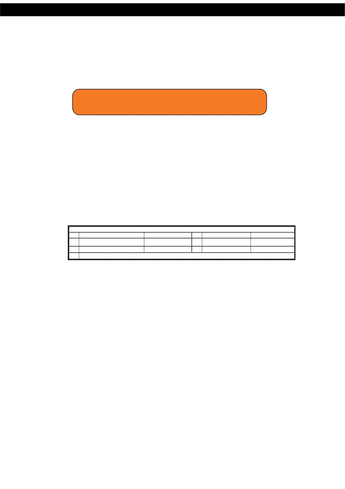
2.12 DIP SWITCH SETTINGS
The A 4505C has various options which are set by the DIP switches on the rear of the unit. These are outlined below and in
gure 2.11.
Switch 1
This switch is used to either loop the Bell/Prebell, or play the Bell/Prebell only once after it has been triggered.
ON = Loop, OFF = Play Once
Switch 2
DIP switch 2 enables or disables the voice over message. The voice-over message is played in between every three cycles of
the Fire tone.
ON = Enabled, OFF = Disabled
Switch 3
This switch can be used to lockout the menu button, to deter tampering with the programmed times.
ON = Menu button disabled, OFF = Menu button enabled
Switch 4
This switch can be used to lockout the front isolate button.
ON = Isolate button disabled, OFF = Isolate button enabled
Switch 5-8 Not Used
Fig 2.11
2.13 24V OUTPUT CONNECTIONS
These contacts can be used for connection of override relays in remote volume controls, or strobes for unusually noisy en-
vironments. An override relay is necessary where attenuators are used so that the Lockdown tone, Fire tone or message is
broadcast at full volume regardless of the volume setting on the individual volume control (attenuator).
Lockdown/Fire 24V Out:
These contacts are for switched 24V outputs whenever the Lockdown or Fire tones are activated. These may be used to run
external systems such as strobes in unusually noisy environments, or override relays in remote volume controls.
When this output becomes active, 24V will appear between the N/O contact and the GND contact. When this output is not
active 24V will appear between the N/C contact and the GND.
Bell 24V Out:
These contacts are for switched 24V outputs whenever the Bell or Relay Only (No MP3 option) are activated These contacts
are for operating an external relay used to operate something like a lunch bell etc.
When this output becomes active, 24V will appear between the N/O contact and the GND contact. When this output is not
active 24V will appear between the N/C contact and the GND.
Common 24V Out:
These contacts are for switched 24V outputs whenever the Lockdown, Fire, Bell, Prebell or Relay Only (No MP3 option) tones
are activated. When this output becomes active, 24V will appear between the N/O contact and the GND contact. When this
output is not active 24V will appear between the N/C contact and the GND.
IMPORTANT NOTE:
Ensure power is switched off when adjusting DIP switches.
New settings will be effective when power is switched back on.
ON OFF
1
3
Disable Menu Options
SW
5-8
NOT USED
Enable Menu Options
Loop PreBell/Bell Until Cancelled Play Prebell/Bell Once
ON OFF
2
Voice Over Enabled
SW
Voice Over Disabled
4
Disable Isolate Switch
Enable Isolate Switch