R3C Radio Guide
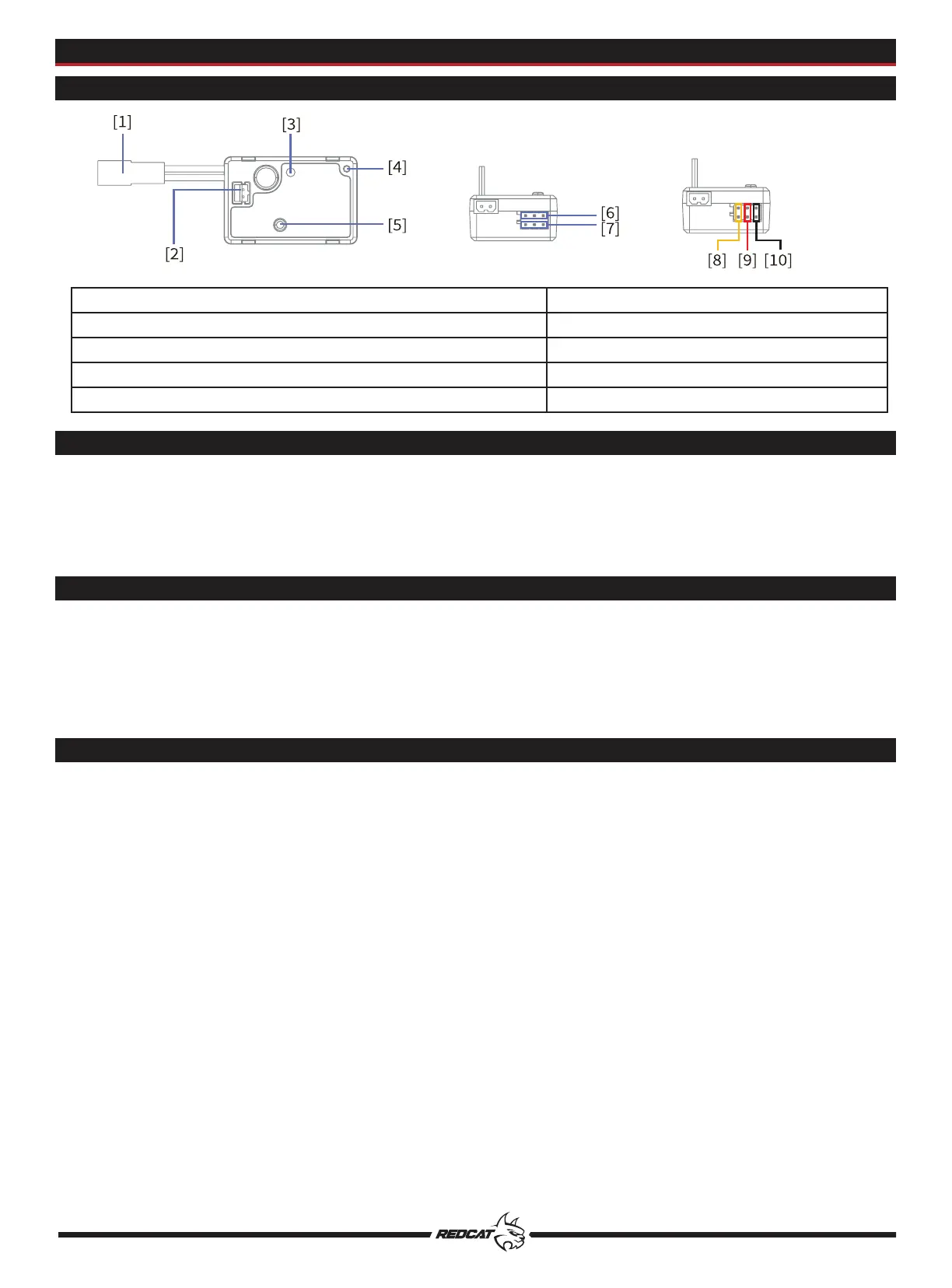
Receiver/ESC Overview
LED
Interface
External Antenna
TM
5
[1] Battery Plug (uses JST connector) [6] CH1 Interface (Steering Servo)
[2] Motor Plug (includes extension w/ 2 blade connectors) [7] CH3 Interface (Aux. Servo)
[3] LED [8] S (Channel Interface Signal Pin)
[4] Antenna [9] + (Channel Interface Anode Pin)
[5] Power Button [10] - (Channel Interface Cathode Pin)
The LED [3] indicates the working state of the receiver/ESC.
OFF: The receiver is not powered on.
ON - Solid: The receiver is on and working normally.
Flashing Quickly: The receiver is in binding mode.
Flashing Slowly: The transmitter is powered off, or the receiver isn’t receiving a signal from the transmitter.
CH1 and CH3 channel interfaces [6] & [7] are standard 2.54mm*3 Pin connectors, which are found on most
common servos.
The battery interface [1] uses a female JST connector. The battery pack must have a male JST connector.
The motor interface [2] includes a female PH2.0 connector that is built into the receiver/ESC. The included
extension uses a male PH2.0 connector on one end and two blade connectors on the other end that connect
to the positive and negative terminals found on the motor.
CAUTION: Do not pull on or bend the receiver’s antenna. Do not fasten the antenna and the servo cable
together.
CAUTION: Keep the receiver's antenna at least 1cm away from conductive materials such as carbon or metal. If
the antenna is too close to conductive materials, it will negatively effect the signal strength of the receiver.