23
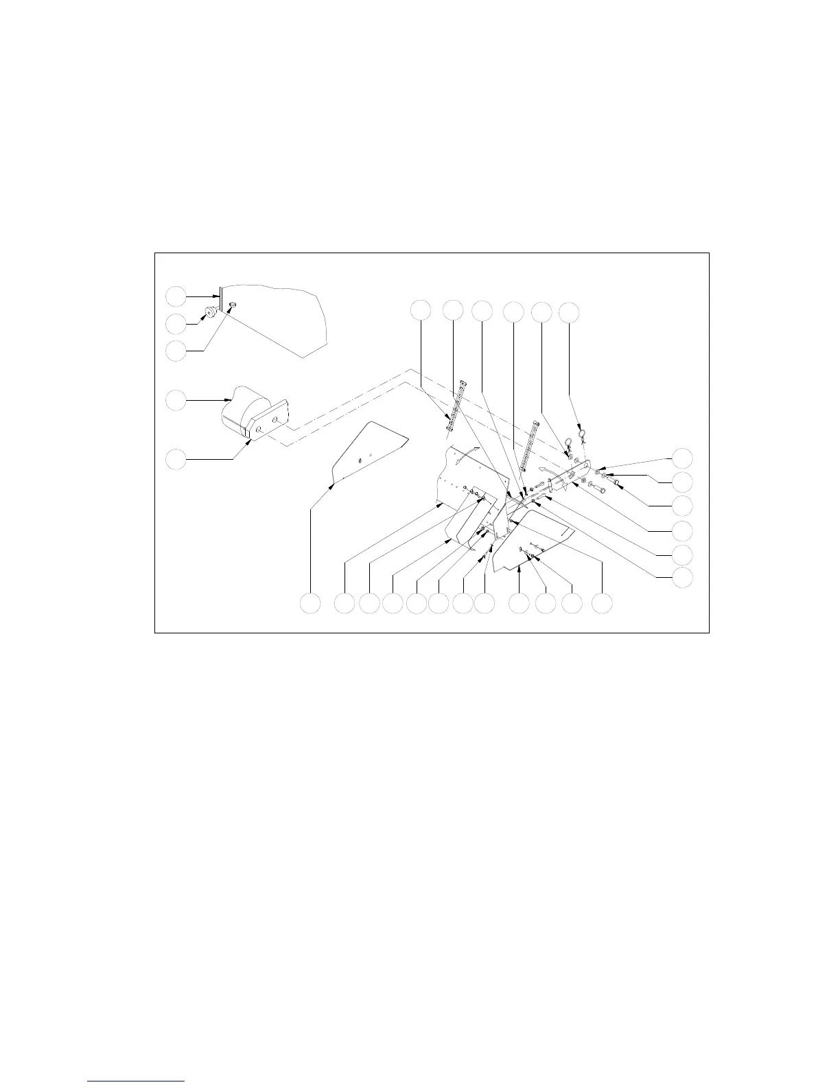
Assembling the core collector itself:
- Assemble supports 17 with eye bolts 9 and nuts 10/11 to the main collector plate 1
- Screw the side panels 2/3 with bolts 7 and Bushes 8 to the main collector plate 1
- Assemble the rubber strip 12 with bolts 13, washers 14 and nuts 6 to the plate 1
- Assemble all the sheet springs 4 , well aligned, to the main plate 1.
@ Choose for the time being the center hole for bolts 7. This setting can be changed later
@ The side panels 2/3 should not be tight, but moveable around the bushes 8.
USER INSTRUCTIONS:
- When the core collector and the Verti-Drain are well prepared, the core collector supports 17 can
be slided (X) onto the bushes 15. Secure it with R pins 19. The rear roller is of the ground, when
the core collector is attached. If the clearance is not enough, do NOT remove the rear roller (since
the weight is needed) but turn the roller up by taking on bearing bolt out.
- The rear roller supports at the machine must float. So don’t lock them with pin 10 (fig.2.)
- Fit chain 20 with two D- shackles to support 17 and eye bolt 24. Ensure left and right are set at the
same length. Allow about 100 mm ( 4”) play, so the core collector can follow the ground perfectly
and is lifted when the machine is raised. When the working depth on the machine is adjusted, the
chain length need to be checked.
- The rubber seal strip 12 is the first and major shovel, that will hold the cores. The ground
clearance should be about the core diameter and can be adjusted by choosing other holes for bolts
7.
- The blade springs 4 act as fine cleaner, because they can individually follow the ground contours.
The pressure can be set by tilting the main body plate 1 forwards or backwards (Y). This can be
achieved by adjusting the top and bottom eye bolt 9 position to the main plate 1.
20
12
14
6
16
19
15
16
17
10
9
18
11
1
5
4 13 14
7
86 62
22
23
26
25
24
3
X
Y
Fig.12.