WARNING
!
• Failure to follow these instructions and warnings may result in malfunction or breakage of this component, possibly
causing serious injury or death.
• Always use a torque wrench when installing or adjusting fasteners, and always tighten to Redshift torque
specications (or the bike manufacturer’s torque specication). Periodically check all fasteners for tightness using a
torque wrench, since fasteners can loosen under the inuence of road vibration.
• Periodically clean and inspect all surfaces of this component for hairline cracks or signs of damage. If you nd
any cracks or damage, immediately cease using the part and contact Redshift Sports customer service.
• Using the ShockStop stem can aect a bicycle’s handling characteristics. Following installation, practice using
the ShockStop at low speed in a safe area to get used to the bicycle’s responsiveness and steering.
• This stem is intended for use only on paved or unpaved roads. O-road use may lead to slippage or breakage of
the component, possibly causing serious injury or death.
BEFORE YOU BEGIN
Before you begin installation, take note of your current stem’s installed orientation and position on the steerer
tube. Most stems can be installed in either the positive or negative orientation in order to adjust the amount of
rise. Headset spacers can also be placed above or below the stem to change its position along the steerer tube.
COMPATIBILITY
• The ShockStop is compatible with drop handlebar and at handlebar setups. The ShockStop is not compatible
with swept back or “cruiser” style handlebars.
• The ShockStop is designed for use on threadless headsets with 1-1/8” steerer tubes. It may be used with
smaller steerer tube diameters by using an appropriate shim.
• If your bike has a quill stem, you will need to install a quill-stem adapter (not included) to use the ShockStop.
TOOLS YOU’LL NEED
• 4mm hex wrench, 3mm hex wrench, torque wrench, bicycle grease.
REMOVE YOUR EXISTING STEM
Note: This section describes the removal process for a typical threadless stem. If your bike has a quill stem, you
will need to install a quill stem adapter (not included) after removing the stem.
1. Unscrew and remove the faceplate bolts and remove the faceplate to separate the handlebar. You can let
the handlebar hang in front of the bike or rest on the front wheel.
2. Loosen the 2 pinch-bolts on your stem’s steerer tube clamp.
3. Unscrew and remove the top cap of the steerer tube.
4. Slide the stem o the steerer tube (along with any spacers that are above the stem).
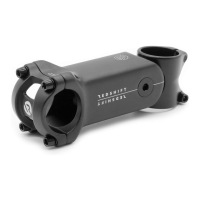
ATTACH THE SHOCKSTOP TO YOUR BICYCLE
The 6 degree ShockStop can be installed in either the +6 degree or -6 degree orientation. In the +6 degree
orientation, the words “Torque, 5.0 N-m” will face upward near the front of the stem tube. In the -6 degree
orientation, the words “+/-6 deg, XX mm” will face upward near the front of the stem tube (where XX is the
length of your stem). The +30 degree ShockStop should only be installed in the +30 orientation.
* ATTENTION: The 6 degree ShockStop stem ships with elastomers installed in the +6 degree orientation. If you ip
the stem to the -6 degree orientation, after attaching it to your bicycle you will need to remove and reinstall the
elastomer(s) and preload wedge so that the elastomers are positioned above the support, as shown in steps 9-14
below.
5. Loosen the two pinch bolts (#6b), and slide the ShockStop steerer tube clamp (#2) onto the steerer tube in
the appropriate orientation (+ or -). Position your bicycle’s headset spacers above or below the stem, as
desired.
6. Make sure that the top headset spacer (or top of the stem if all spacers are positioned below the stem) is
slightly above (about 2-3mm) the top of the steerer tube.
7. Very lightly tighten the 2 pinch bolts (#6b) on the ShockStop in order to keep it from easily sliding back and
forth on the steerer tube.
8. Lightly screw the top cap onto the steerer tube until it begins to tighten.
ADJUST ELASTOMER STIFFNESS
WARNING! The ShockStop MUST BE INSTALLED ON YOUR BIKE WHEN INSTALLING THE PRELOAD
WEDGE BOLT (step 13). This is required so that you can apply downward force to the stem to slightly
compress the elastomers while inserting the preload bolt. Failure to apply downward force while
installing the preload bolt (#7) may cause the bolt to PERMANENTLY DAMAGE the threaded hole in the
steerer tube clamp (#2) rendering the stem UNUSABLE.
9. Using a 4mm hex wrench, loosen and remove the four faceplate bolts (#6a) and remove the faceplate (#5)
and handlebar (if installed).
10. Using a 3mm hex wrench, loosen and completely remove the preload bolt (#7) and wedge (#8). The bolt
will require about 32 turns to fully remove the wedge. The bolt will remain captured in the wedge.
11. Pull upward on the stem and remove the elastomer(s) (#4) from inside the stem. You may need to use the
small end of your hex wrench to hook the handle of the elastomer to pull it out.
12. Select an elastomer combination from the chart on the follwing page and insert the appropriate
elastomer(s) into one or both of the upper elastomer pockets. It may help to push the stem tube (#1) to the
top of its travel while inserting the elastomers. Be sure to insert the elastomers (#4) in the orientation
shown below (handle towards the outside), so as not to interfere with the preload wedge (#8) installation.
# QTY PART NAME
6a 4 Faceplate Bolt (M5 x 18 mm)
6b 2 Pinch Bolt (M5 x 18 mm)
8 1 Preload Wedge
9 6 Lock Washer
SHOCKSTOP
SUSPENSION STEM
INSTRUCTIONS
Thank you for purchasing the ShockStop Suspension Stem. This
stem is dierent than other stems, so please read these instructions
and warnings completely before installing or using it. If you are
unfamiliar with bike maintenance or stem installation, or if you lack
the required tools, please visit your local bike shop or contact
Redshift Sports customer service for assistance. Improper
installation or use may void the product’s warranty policy and may
lead to serious injury or death.
For the most up-to-date instructions, instructional videos
and additional resources, visit www.redshiftsports.com.
2
8
1
5
6a
7
4
3
6b
9