EasyManua.ls Logo

REDSHIFT ShockStop - User Manual

REDSHIFT ShockStop
2 pages
Print Icon
To Next Page IconTo Next Page
Loading...
SHOCKSTOP SEATPOST
INSTRUCTIONS
WARNING
!
• Failure to follow these instructions and warnings may result in malfunction or breakage of this component,
possibly causing serious injury or death.
• Always use a torque wrench when installing or adjusting fasteners, and always tighten to Redshift torque
specications (or the bike manufacturer’s torque specication). Periodically check all fasteners for tightness
using a torque wrench, since fasteners can loosen under the inuence of road vibration.
• This seatpost is designed for use in a 27.2 mm diameter seatpost. It may be used with larger seat tube
diameters by using an appropriate diameter shim longer than 100mm (4 in.) in length.
• Do not raise the post beyond the minimum insertion line.
• Periodically clean and inspect all surfaces of this component for hairline cracks or signs of damage. If you nd
any cracks or damage, immediately cease using the part and contact Redshift Sports customer service.
• This seatpost is intended for road and light o-road use only. It is NOT intended for extreme o-road use or
jumping. Unintended use may lead to breakage of the component, possibly causing serious injury or death.
• Never place your hands or ngers near the seatpost linkages while riding. Doing so may cause pinching or
crushing injuries.
• For metal-framed bicycles, ensure that the post and the inside of the seat tube are covered with a thin layer of
bicycle grease prior to installation. Failure to do so may cause the post to seize inside the bicycle frame.
Thanks for choosing the Redshift Sports
ShockStop Suspension Seatpost! The
seatpost provides tunable suspension to
increase comfort and performance
during your ride.
This seatpost is dierent than other
seatposts, so please read these
instructions and warnings completely
before installing or using the seatpost. If
you are unfamiliar with bike
maintenance or seatpost installation, or
if you lack the required tools, please visit
your local bike shop or contact Redshift
Sports customer service for assistance
(support@redshiftsports.com). Improper
installation or use may void the
product’s warranty.
Check out www.redshiftsports.com/faq
for instructional videos and additional
resources.
CHANGING SPRINGS
The ShockStop Seatpost ships with 2 springs – an outer spring which
comes pre-installed in the seatpost, and an inner spring which is
included in the package.
NOTE: THE OUTER SPRING MUST ALWAYS BE INSTALLED. The
inner spring can be optionally added when a stier spring rate is
desired.
COMPATIBILITY
This seatpost is designed for bicycle
frames with a 27.2mm diameter
circular seat tube. The seatpost may be
used with larger diameter seat tubes by
using the correct diameter seatpost
shim. In order to reduce stresses on the
post and frame, only use seatpost
shims of at least 100 mm (4 in.) in
length. Using the seatpost in a dierent
diameter seat tube without an
appropriate shim may cause damage or
failure of the seatpost or bicycle frame.
CHOOSING YOUR SEATPOST SETUP
The Shockstop seatpost is fully adjustable to t you and
your riding preference. Dierent springs can be used to
make large adjustments to the stiness, and then
ne-tuning can be accomplished by adjusting the preload
plug located at the bottom of the seatpost.
The chart shown here is a good starting point, but
dierent riders may prefer stier or softer settings
than the chart recommends. Riding position and
terrain can also dramatically aect the required preload
setting, so don’t be afraid to experiment with dierent
settings to nd your best ride!
*When using the Main Spring Only, the maximum recommended preload
setting is 4. Riders needing more preload should add the Inner Spring and
start at a lower preload setting.
Preload Plug
Spacer Tube
End Cap
End Cap
Main Spring
Optional
Inner Spring
(place inside
Main Spring)
5
11
10
9
9
8
7
2
3
6
4
1
# QTY PART NAME
1 1 Seatpost & Linkage
2 1 Lower Saddle Clamp
3 1 Upper Saddle Clamp
4 2 Saddle Clamp Nuts
5 2 Saddle Clamp Bolts
6
1 Fender
7 1 Preload Adjustment Plug
8 1 Spring Spacer
9 2 Spring Endcap
10
1 Main Spring
11 1 Inner Spring (Op�onal)
RIDER WEIGHT SPRING SETUP
SUGGESTED
INITIAL PRELOAD
< 110 lb / 50 kg Main Spring Only 1
132lb / 60 kg Main Spring Only 2
154 lb / 70 kg Main Spring Only 3
176 lb / 80 kg Main Spring Only 4*
198 lb / 90 kg Main + Inner Spring 2
220 lb / 100 kg Main + Inner Spring 3
242 lb / 110 kg
(max)
Main + Inner Spring 4
1. Remove seatpost from frame.
2. Turn seatpost upside-down and completely unscrew the preload plug.
This can be done by hand or by inserting a 4 mm hex wrench through
the side holes in the plug to provide additional leverage.
3. Tilt seatpost to slide internal components out the bottom of the
seatpost: spring spacer, spring(s) and spring end caps.
4. Insert or remove the inner spring inside the outer spring
5. Apply grease to the outside of the outer spring and spring end caps, if
needed.
6. Turn seatpost upside-down again and reinstall the internal
components, noting the order in the picture. The protective material
around the outer spring should be oriented towards the top of the
seatpost. The spring end caps should be sitting at against the
spring. When fully installed, the spacer tube should sit a few
millimeters inset from the bottom of the seatpost. If the spacer tube
is protruding from the bottom of the post, make sure the suspension
linkages are fully extended and make sure the spring end caps are
sitting at against the spring.
7. Re-install preload plug and adjust as-needed for desired suspension
rmness.
NOTE: The ShockStop Seatpost Di2 Battery
Holder Accessory (sold separately) will allow
you to securely mount a Di2 battery in the
bottom of the seatpost.
Question and Answer IconNeed help?

Do you have a question about the REDSHIFT ShockStop and is the answer not in the manual?

Summary

Choosing Your Seatpost Setup

Changing Springs

Instructions for installing or removing the inner spring to adjust suspension stiffness.

Compatibility

Details on seatpost compatibility with various frame diameters and required shim usage.

Safety Warnings

Critical safety warnings regarding installation, use, and potential hazards of the seatpost.

Setting the Preload and Installation

Setting the Preload

Guidance on adjusting preload for desired suspension sag and firmness using visual cues.

Installing the Seatpost

Step-by-step instructions for securely installing the seatpost into the bicycle's seat tube.

Warranty Information

Details Redshift Sports LLC's two-year warranty terms and conditions for the seatpost.

Maintenance Guidelines

Recommendations for maintaining the seatpost, including lubrication advice for optimal performance.

Overview

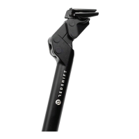
The Redshift ShockStop Suspension Seatpost is a bicycle component designed to enhance riding comfort and performance by providing tunable suspension. It is specifically engineered for bicycle frames with a 27.2mm circular seat tube, though it can be used with larger diameter seat tubes by employing an appropriate diameter shim at least 100mm (4 inches) in length.

Function Description

The core function of the ShockStop Seatpost is to absorb road vibrations and impacts, thereby reducing rider fatigue and improving control. This is achieved through an internal suspension mechanism that utilizes springs and a linkage system. The seatpost's suspension is fully adjustable to suit individual rider weight and preference, allowing for a customized riding experience.

Usage Features

The seatpost's suspension stiffness can be adjusted in two primary ways: by changing the internal springs and by adjusting the preload plug.

  1. Spring Selection: The seatpost comes with two springs: an outer spring (pre-installed) and an inner spring (included in the package). The outer spring must always be installed. The inner spring can be optionally added to achieve a stiffer spring rate, which is often desired by heavier riders or those preferring a firmer suspension feel. The process involves removing the seatpost from the frame, unscrewing the preload plug, and then tilting the seatpost to slide out the internal components (spring spacer, springs, and spring end caps). The inner spring is then inserted inside the outer spring, and the components are reinstalled in the correct order, ensuring the protective material around the outer spring is oriented towards the top of the seatpost and the spring end caps sit flat against the spring. Grease should be applied to the outside of the outer spring and spring end caps if needed during reinstallation.

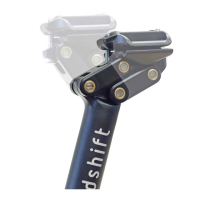
  2. Preload Adjustment: Fine-tuning of the suspension stiffness is accomplished by adjusting the preload plug located at the bottom of the seatpost. Turning the preload plug further into the seatpost increases stiffness, while unscrewing it softens the suspension. This adjustment can be made by hand or, for additional leverage, by inserting a 4mm hex wrench through the side holes in the plug. It's crucial not to set the preload adjustment below the "1" mark, as this can cause internal parts to loosen or fall out during riding. The firmest setting is achieved when the preload plug is turned all the way in.

    A general guideline for setting the preload is to adjust it so that the suspension mechanism moves down approximately 6mm (20%) from the top of its travel range when the rider is in a neutral riding position. This 20% sag point can be visually determined by removing the fender and observing the linkage pivot shaft from the side. The preload should be set so that the end of the silver pivot shaft is barely (but completely) hidden from view when seated. Another method is the "bounce test": while riding on flat ground, raising up off the saddle and then sitting down with some force to bounce the suspension. If it's easy to reach the full range of travel and a noticeable "bottom-out" is felt, the preload should be increased.

Installation and Saddle Setup:

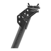
Before installation, it's recommended to measure and record the existing saddle height, fore-aft position, and tilt angle for future reference. The existing seatpost and saddle should be removed, and the inside of the bicycle's seat tube cleaned and greased (unless it's a carbon frame and specified otherwise by the manufacturer). The ShockStop Seatpost is then inserted into the seat tube to the desired height, ensuring the minimum insertion line is not visible above the frame's seatpost clamp. The seatpost clamp bolt should be tightened according to the bicycle manufacturer's torque specification.

Saddle installation involves loosening the saddle clamp bolts with a 4mm hex wrench until the threads are barely engaged in the nuts, then installing the saddle between the upper and lower clamp. The lower clamp should be positioned with the longer rail supports toward the back of the saddle. If installing the seatpost fender, the rear saddle clamp bolt must be completely removed, the fender o-ring looped around the bolt under the upper saddle clamp, and the bolt reinstalled. The front and rear clamp bolts are then lightly tightened to hold the saddle in place. The saddle's fore-aft position is adjusted within the clamp.

Saddle angle adjustment is achieved by tightening or loosening the front or rear saddle clamp bolts. Once the desired angle is set, both bolts are alternately tightened in quarter-turn increments using a torque wrench for the front bolt and a standard hex wrench for the rear bolt. The front bolt should reach 6 N-m of torque, not exceeding 9 N-m. It is crucial to avoid over-tightening saddle clamp bolts, as this can lead to seatpost failure. When tightening the rear bolt (tilting rearward), the upper saddle clamp must not contact the rear portion of the linkage mechanism. When tightening the front bolt (tilting forward), there must be a gap of at least 2mm between the upper saddle clamp and the upper linkage. Finally, the fender is installed against the rear linkage by placing its magnet on the front saddle clamp bolt, and saddle height is adjusted if necessary.

Maintenance Features

The ShockStop Seatpost is designed for quiet and smooth operation with minimal maintenance. Users are advised to periodically clean and inspect all surfaces for hairline cracks or signs of damage. Any detected cracks or damage necessitate immediate cessation of use and contact with Redshift Sports customer service.

It is important not to use grease or any lubrication on the pivot bushings, as they are designed to run dry and will perform better and last longer without lubricant.
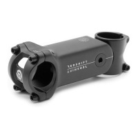
Safety Warnings

  • Failure to follow instructions and warnings can lead to malfunction, breakage, serious injury, or death.
  • Always use a torque wrench for fasteners and periodically check all fasteners for tightness.
  • The seatpost is designed for 27.2mm seat tubes; use of an appropriate shim (at least 100mm/4in) is required for larger seat tubes.
  • Do not raise the post beyond the minimum insertion line.
  • The seatpost is intended for road and light off-road use only, not for extreme off-road use or jumping.
  • Never place hands or fingers near the seatpost linkages while riding to avoid pinching or crushing injuries.
  • For metal-framed bicycles, ensure the post and the inside of the seat tube are covered with a thin layer of bicycle grease prior to installation to prevent seizing.
  • Do not over-tighten saddle clamp bolts.

REDSHIFT ShockStop Specifications

General IconGeneral
TypeSuspension Stem
TravelUp to 20mm
Handlebar Clamp Diameter31.8mm
Length Options80mm, 90mm, 100mm, 110mm, 120mm
UseRoad, Gravel, Commuting
Suspension Travel20mm
Steerer Tube Diameter1-1/8 inches
Angle6 degrees
CompatibilityCompatible with standard 1-1/8" steerer tubes
Diameter31.8mm (handlebar clamp)
Material6061 T6 Aluminum

Related product manuals