6
(Reel Rollers Superstore – 2333 Peachtree Industrial Blvd, Buford, Georgia 30519 – www.reelrollers.com)
019116 R/MWR MAS 660 RRR H USA BLK- Jan 24
Assembly Instructions
LOWER HANDLE.
To facilitate shipping the handle is not attached to the mower. It has
two parts, an upper and a lower one. Fit the lower handle (the one
without a hand grip) rst. It does not matter which way around it is
tted. Bolt it loosely to the lugs at the rear of the mower using the
four bolts provided. Note that the lower bolts pass through slots to
provide adjustment for the handle height. After tting the upper
handle, adjust it to the desired height and tighten all four bolts rmly
UPPER HANDLE.
Keeping the upturned handle grip on top, t the lower ends of the
top handle over the bottom handle and align the holes for the cam
locks.
Remove the nut and washer from the Folding Handlebar levers bolt
but leave the rectangular wear plate in position as you pass the bolt
through the holes from the outside. The attened part of the bolt ts
the slot in the upper handle. While the lever will work with the bolt
tted either way in the slot, we suggest tting the bolt so that the
lever will point to the top of the handle when locked. Fit the washer
and nut on the inside of the bolt and adjust the nut to give the de-
sired clamping action. Fit the second cam lock in the same way.
USING THE ‘FOLDING HANDLEBAR’ LEVERS.
Swing the upper handle to the operating position and lock it in
place by pushing the Lever(s) upwards towards the upper handle.
The rmness of the locking action can be adjusted by turning the
nut on the inside of the lever bolt.
Swing upward to lock
THE LEVERS ON SOME MOWERS ARE REVERSED FOR
SHIPPING.
To turn them around unwind the nut to the end of the thread with a
13mm socket, pull the lever outwards and rotate in 180. Retighten
the nut until the handle locks rmly in place and it does not change
position when in use.
•
•
•
•
•
•
•
et, pull the
ards and
ut
mly in
ATTACHING THE CABLES
All models have three cables that need to be attached:
1. The engine throttle control cable.
2. The roller clutch cable.
3. The Reel clutch cable
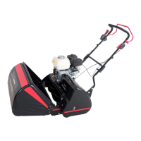
1. THE ENGINE THROTTLE CONTOL CABLE.
The control lever housing must be tted to the outside of the upper
handle. The cable will have a retainer that ts under the left-hand
cam lock levers nut& washer. Loosen the nut and screw and t it to
the outside left-hand side of the handle and tighten the nut & screw.
When doing this, ensure the control cable runs above the lower
handle cross bar to avoid damaging the cable when the handle is
folded for storage.
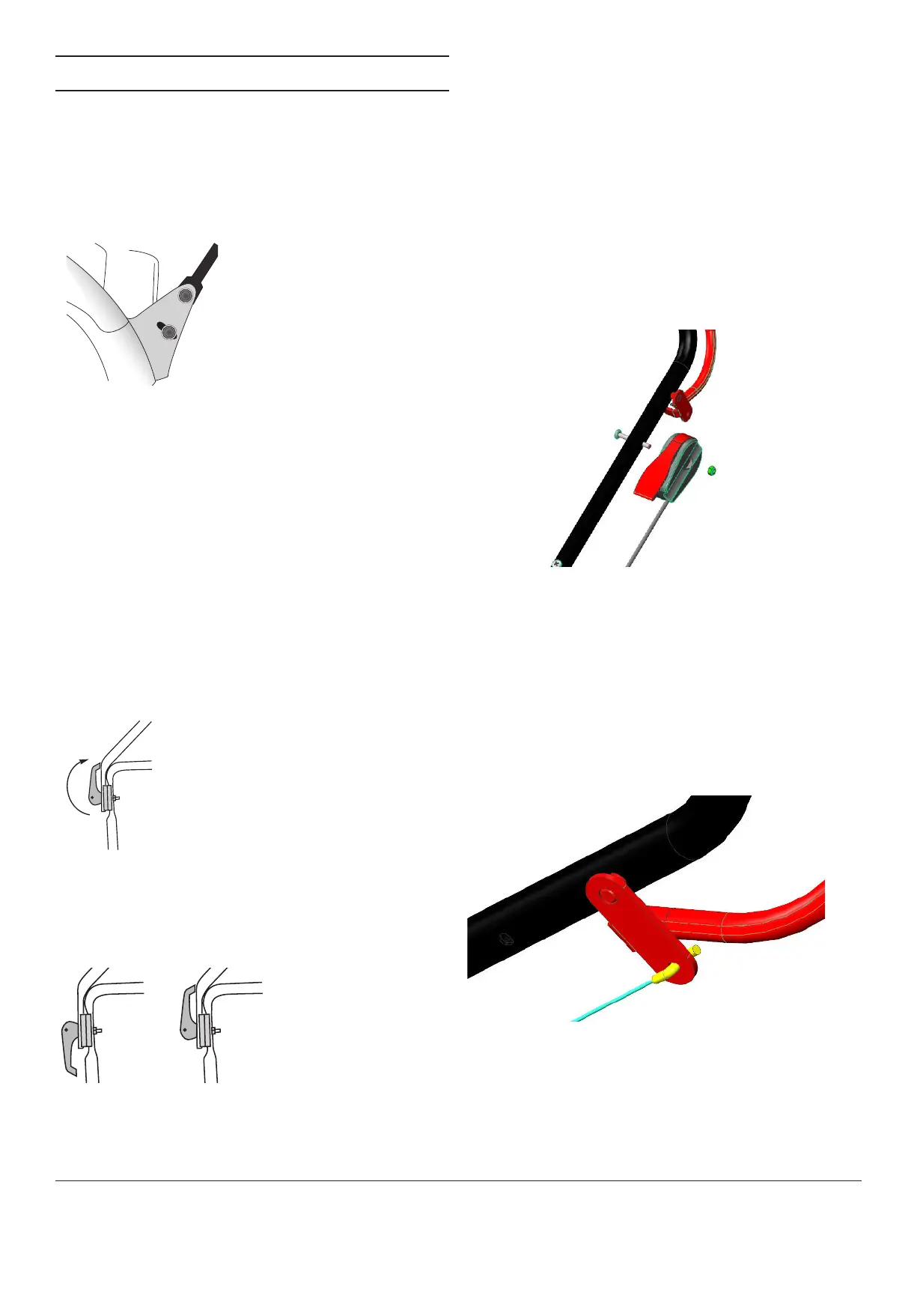
2. FITTNG THE GROUND SPEED CUTCH CABLE.
The cable will be already attached to the mover at the lower end.
The clutch cable is the one that enters the mower under the shaft
cover the other end has a ‘z’ bend tting. With the cable running
above the cross bar of the lower handle, feed the end of the ‘z’
tting though the small hole in the roller clutch bail, found below
the handle. Turn the ‘z’ tting so the cable is running alongside the
upper handle.
 Loading...