Brushless-Set „Cheetah“ 60 A
Item no. 1348619
Intended Use
The electronic speed controller and the brushless motor in the set serve to drive buggy and touring car model
vehicles at a scale of 1:10 or 1:12 and in Crawler model vehicles at a scale of 1:10 and 1:8.
Depending on the model vehicle, the speed controller and the brushless motor can be operated with a NiMH
drive battery with 6 - 9 cells or a LiPo drive battery with 2 - 3 cells.
The speed controller can be programmed via an enclosed programming card.
To control the sped controller, it is connected to a receiver of a model remote control system (at the control
channel for the driving function).
The safety notes and all other information in these operating instructions always have to be observed.
This product complies with the statutory national and European requirements. All company names and pro-
duct names are trademarks of their respective owners. All rights reserved.
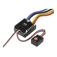
Scope of Delivery
• SpeedController
• Brushlessmotor
• Sensorcable
• Fanwith4attachmentscrews
• Programmingcard
• Connectioncableforprogrammingcard
• OperatingInstructions
Safety Information
In case of damage caused by non-compliance with these operating instructions, the war-
ranty/guarantee will expire. We do not assume any liability for consequential damage!
Nor do we assume any liability for damage to property or personal injury caused by impro-
per use or failure to observe the safety instructions. In such cases the guarantee/warranty
will expire!
• Theunauthorizedconversionand/ormodicationoftheproductisprohibitedforsafetyandapprovalre-
asons (CE). Never disassemble the product. There are no components inside the casing that need to be
adjustedorservicedbyyou.Furthermore,thiswillrendertheguarantee/warrantyvoid!
• Thisproductisnotatoyandnotsuitableforchildren.
• Alwaysturnonthetransmitterrstandputitsoperatingleverforthedriving/brakingfunctionintoneu-
tral position. Then the speed controller may be connected to a driving battery and switched on. When
switchingoff,proceedinthereverseorder.Beforeturningoffthetransmitter,turnoffthespeedcontroller
and, if necessary, disconnect it from the drive battery.
• Disconnectthedrivebatteryfromthespeedcontrollerifyoudonotneedthespeedcontroller.Thespeed
controllercanbetemporarilyswitchedoffusingtheon/offswitch.
• Thespeedcontrollercanbeusedwitha6-9-cellNiMHdrivebatteryora2-3-cellLiPodrivebattery.
However, always observe when selecting the drive batteries that the drive of the vehicle (e.g. differential)
is not overloaded.
• Thespeedcontroller,themotorconnectedtoitandthedrivebatterywillbecomeveryhotduringoperation.
Riskofburns!
• Alwaysuseabatterypacktooperatethespeedcontroller.Neveruseawallmainsadapter.
• Connectonlytheenclosedbrushlessmotortothespeedcontroller,butnoothermotor.
• Wheninstalling,keepthegreatestpossibledistancebetweenthereceiverandthespeedcontroller/motor
to avoid interference.
• Donotinstalltheaeriallineofthereceiverinparalleltothelivecables.
• Whenoperatingthemodel,sufcientcoolinghastobeprovidedforthespeedcontrolleraswellasthe
motor.Installtheenclosedfanbeforecommissioningthespeedcontroller.
• Checktheventilatorfunctionateverycommissioning,donotblockthefan,removedustandcontaminati-
on, that has collected there, e.g. by operation of the vehicle, from the fan.
• Observethatthereisneveranybodypartorobjectinthedangerareaofturningpartsofthevehicleor
drive.Riskofinjury!
• Donotblockthedrive.Theresultingcurrentsmaydestroythemotorand/orspeedcontroller.
• Observeasmoothdrivesectionandperformregularmaintenance.
• Regularlycheckthevehicle,speedcontrollerandmotorfordamage.Ifyoudiscoveranydamage,donot
operatethevehicleorthespeedcontroller/motoranymore.
• Disconnectthebatteryfromthespeedcontrollerbeforecharging.
• Handletheproductwithcare;impacts,shockorfallevenfromlowheightswilldamageit.
• Donotleavepackagingmaterialunattended.Itmaybecomeadangeroustoyforchildren.
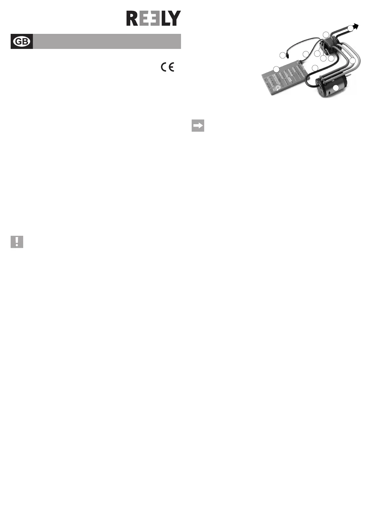
Connections and Control Elements
1 SpeedController
2 Brushlessmotor
3 Programming card
4 Connection cable for programming
card
5 Sensorcable
6 Servoplug forconnection tothe re-
ceiver
7 Two-pin socket to connect the enc-
losed fan
8 Sockettoconnecttheprogramming
card
9 Operatingbutton,withintegratedLED
10Powercable/plugtoconnecttothedrivebattery
11 Connection cable between motor and speed controller
The connection of the programming card and the associated cable is only required for programing
the special functions.
Forregularoperationofthespeedcontroller/motorortoprogrammetheneutralpositionandthe
fullthrottlepositionatforward/reverseoperation,theprogrammingcardmustnotbeconnectedto
thespeedcontroller!
Installation and Connection
• Ifthesetistobeusedasareplacementforanexistingdrive,rstremovetheoldspeedcontroller/motor
from your model vehicle.
• First,attachtheseparatelyenclosedfantothecoolingbodyofthespeedcontroller(1)with4screws.
Connect the two-pole plug to the associated socket (7) of the speed controller.
• Installthedrivepiniononthedriveaxleofthebrushlessmotor.
• Insertthebrushlessmotor(2)inyourvehicleandscrewiton.Observethatthescrewsarenottoolongand
do not fasten or damage the rotating rotor in the brushless motor.
Also observe that the drive pinion is aligned precisely with the main pinion and is not offset to the side.
The distance between the drive pinion and the main pinion must be set so that the drive does not run too
stifybutthepinionsalsoarenottoofarapart.Turnintheattachmentscrewsofthemotorsothatthemotor
does not wobble but can still be moved. Then put a narrow strip of 80 g paper (e.g. toilet paper) between
the drive pinion and the main pinion. Now move the main pinion so that the paper strip is pulled in between
the two pinions.
Now turn the attachment screws of the motor on and remove the paper strip. The distance should be set
perfectly now.
• Connectthethreecables(11)betweenthespeedcontrollerandthemotor;observepropercolourassign-
ment. The rotating direction of the motor can later be set via the programming card.
• Connectthesensorconnectionsofthemotorandthespeedcontrollerwiththesensorcable(5).Theplug
orsocketsareprotectedagainstpolarityreversal;donotapplyanyforceforconnection!
• Installthespeedcontrollerinthemodelvehicle.Ideally,thespeedcontrollershouldbeasfarawayfrom
thereceiverormotoraspossible.Thereceivershouldnotbedirectlynexttothemotoreither.
You may use, e.g., hook-and-loop tape or double-sided adhesive tape (but never hot or superglue, etc.) to
attachthespeedcontroller(andthePCBwiththeinputcapacitor).
Observethatthefunctionofthefanonthespeedcontrollerisnotimpaired.
• Connectthethree-pinservoplug(6)ofthespeedcontrollertothereceiveroutputthatprovidesthecontrol
signals for the drive function.
Always make sure the assignment of the plug contacts on the receiver is correct (see operating instruc-
tionsofthereceiveraswellastheinformationonthereceiver).Ofcourse,thisalsoappliestothesteering
servo of your model vehicle.
Yellow/white/orangecable: Controlsignal
Redcable: Operatingvoltage
Brown/blackcable: Minus/GND
• Installallcablessothattheycannotbecomeentangledinrotatingormovingpartsofthevehicle.Usecable
ties to secure them.
• SincethespeedcontrollerisequippedwithaBECelectronic,noreceiverbatteryorrechargeablebattery
maybeused!Boththereceiverandtheconnectedservo(e.g.thesteeringservo)aresuppliedwithvolta-
ge/powerdirectlyfromthespeedcontrollerviathedrivebattery.
Programming the Speed Controller
You must programme the speed controller after installation before it is ready for use.
Therststepisprogramingtheneutralpositionandthefullthrottlepositionforforwardandreversedriving.
Thisdoesnotrequiretheprogramingcard.Itmustnotbeconnectedtothespeedcontrollereither.
Inthesecondstep,thedifferentfunctionscanbesetviatheprogrammingcard.Itisveryimportanttopro-
gramme the deactivation voltage if you are using a LiPo drive battery to operate the model vehicle.
a) Programming of Neutral and Full Throttle Positions
Thismustbedonerstafterinstallationofthespeedcontroller/motorinthemodelvehiclesothatthespeed
controller can react correctly to the remote control system (transmitter) used by you.
Reprogramming may be required, e.g, if you want to use a different transmitter or if the trimming path at the
transmitterisnolongersufcient.
Version 06/15
Operating Instructions
www.conrad.com
 Loading...