15
QUICK USER GUIDE
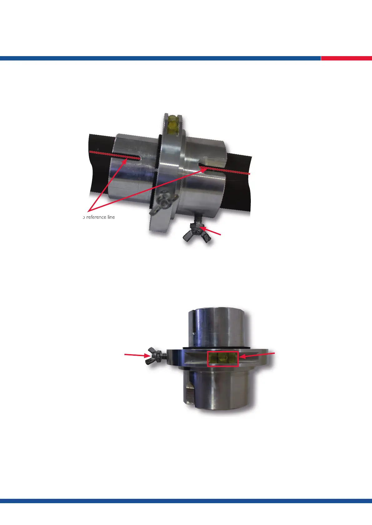
5. Tighten the wing nut on the device body to lock it to the core inner tube (Fig. 3).
6. Retrieve orientation information from ACT III RD as per normal procedure.
7. Once bottom of hole orientation is achieved keep the core inner tube still while rotating the levelling wheel of the transfer device until the
levelling bubble is in between the black lines. Once there tighten the levelling wheel wing nut to lock the wheel (Fig. 4).
8. Undo device body locking nut and remove from core inner tube and place over the reference line of the second inner tube at the opposite end
to the core lifter case.
9. Rotate the transfer device until the reference line appears within the reference slots and tighten the wing nut to lock the transfer device to the
inner tube (Fig. 3).
N.B. DO NOT undo the levelling wheel wing nut.
10. Roll the core inner tube until the bubble is between the two black lines (Fig. 4).
11. Holding the core inner tube still, proceed to mark the bottom of hole orientation as per the normal procedure.
reference slots aligned to reference line
reference slots aligned to reference line
If possible, add the inner tube with ACT III RD
Tighten wing nut on device body to core inner tube
Fig. 3
tighten wing nut on levelling wheel once
bubble is within black lines
ensure bubble is between
the black lines
Fig. 4