7
QUICK USER GUIDE
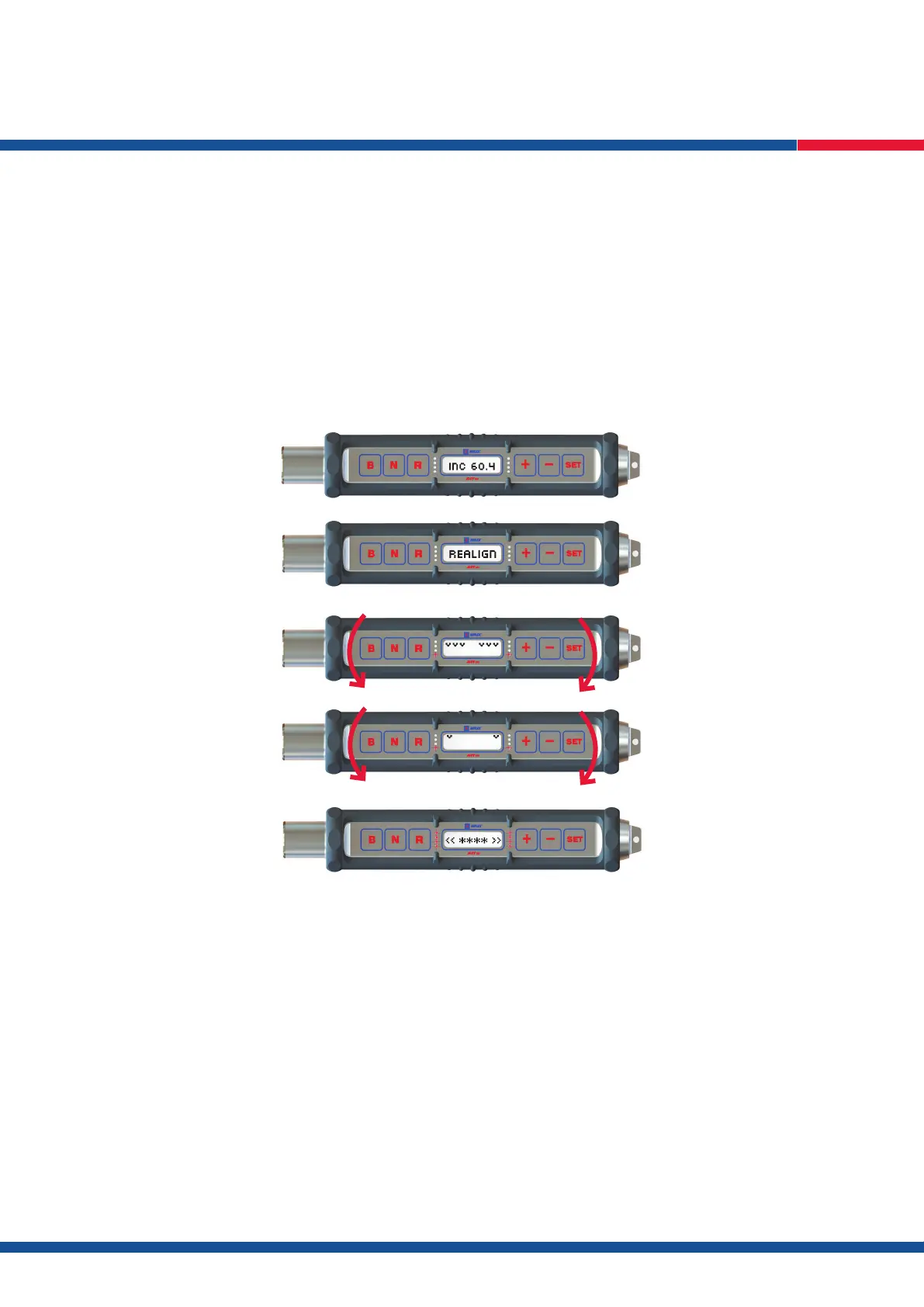
3.4. Press R again to display the dip/inclination, e.g. INC 60.4 (Fig. 27).
3.5. Press the R button once more to retrieve orientation – REALIGN will display for 2 seconds followed by the directional arrows on the LCD
screen (Fig. 28).
3.6. With the ACT III RD controller still connected to the Infra Red Port the inner tube assembly should be rotated in the direction of the arrows and
red LEDs are indicating (Fig. 29).
As the bottom of hole orientation position approaches the LCD arrows will reduce from 3 each side (Fig. 29) to 1 (Fig. 30).
N.B. The ACT III RD controller should be held still while only the inner tube assembly is rotated.
3.7. When the inner tube assembly has been rotated to the bottom of hole position the LCD screen will display 2 arrows each side of the
screen (Fig. 31) and all LEDs will ash. This indicates bottom of hole orientation has been achieved and can now be transferred to the core.
4. Transferring Orientation to the Core
N.B. Bottom hole orientation can now be transferred to the core as per the procedure mentioned in Section 1, item 7 on page 5.
Fig. 27
Fig. 28
Fig. 29
Fig. 30
Fig. 31