© 2006 GE ECM by Regal-Beloit
- 24 -
Indoor Blower Motors
v0.2
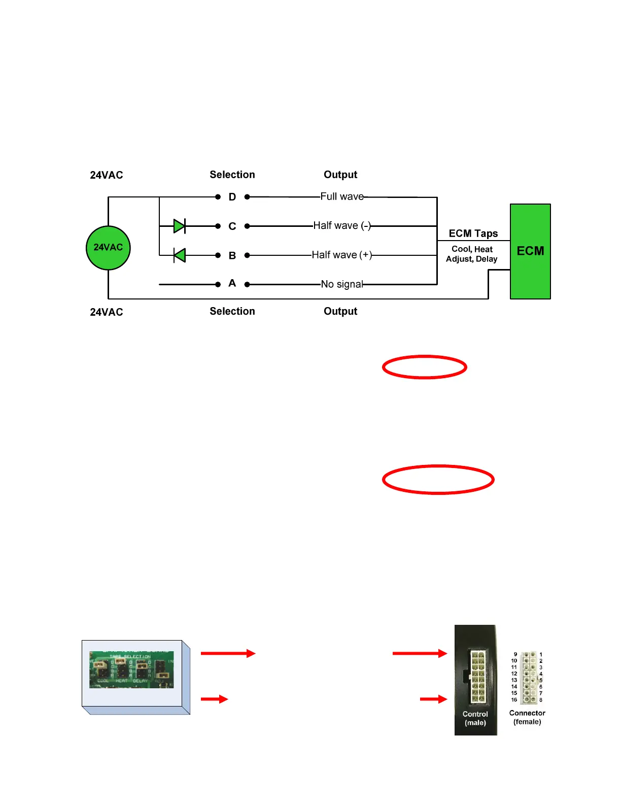
The interface selections choose which circuit to send the signal through to the motor
control. Each circuit is set up to send a different signal to the motor control. The
motor control is programmed to deliver a different pre-programmed airflow for each
signal.
- Constant fan may be preset or field selectable.
Converting one input signal into four different output signals is accomplished with the use of
rectifiers.
The demand taps are W/W1, EM/W2, Y1, Y/Y2, G and Humidistat.
The mode taps are Heat, Cool, Delay and Adjust (tap select)
ECM 2.0 & 2.3
Motor Control
Interface Board
Pin number
1
2
3
4
5
6
7
8
9
10
11
12
13
14
15
Common C1
W/W1
Common C2
Y1
Output -
Return valve (heat pump only)
2
nd
2
nd
A demand for first stage heat sends 24vac from the
interface board to terminal 2 (W/W1).
The OEM manual says to select tap (B) for proper
airflow in first stage heat.
The interface board sends 24vac through the (B)
circuit converting it to a 24vdc+ signal that is sent
to the motor on terminal 11 (Heat tap select).
The motor operates at the stored programmed
airflow that matches that signal in the first stage
heat mode.
24vac to demand tap
A, B, C or D signal to mode tap


 To Next Page