© 2006 GE ECM by Regal-Beloit
- 85 -
Indoor Blower Motors
v0.2
From what we have learned so far, we see that troubleshooting this motor will be
fairly simple as long as the following information is known from the manufactures
manuals:
- Which tap(s) have programs and what are their purposes (heating airflow,
cooling airflow, continuous fan airflow).
- Where on the manufacturer’s controls or circuit board the line voltage and
control voltage come from.
- The sequence of operation of the manufacturer’s controls or circuit board (when
the control voltage is sent to the motor from each thermostat demand and if
there are any delays).
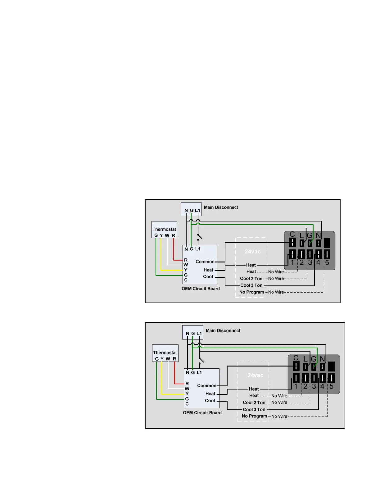
Here are some examples of schematics showing the X13 motor and potential
manufacturer’s connections on a gas furnace.
Some manufacturers
may choose to have
wires connected to all of
the programmed taps
with the unused wires
loose or connected to un-
powered terminals on the
circuit board sometimes
called “unused”,
“dummy”, or “park”. This
makes it easier for the
technician to make
airflow changes at the
circuit board.
Others may chose to
only connect the wires
that are powered.
Changing the airflow is
then done at the motor
taps.
 Loading...