CHAPTER 4
4-4
The standard wire color, gauge size and function shown is used
throughout the marine industr
y. The charts are helpful in identifying
wire circuitry during troubleshooting or the adding of marine
accessories. Never replace a wire with a size other than shown in the
chart. This practice could result in fi re or component failure.
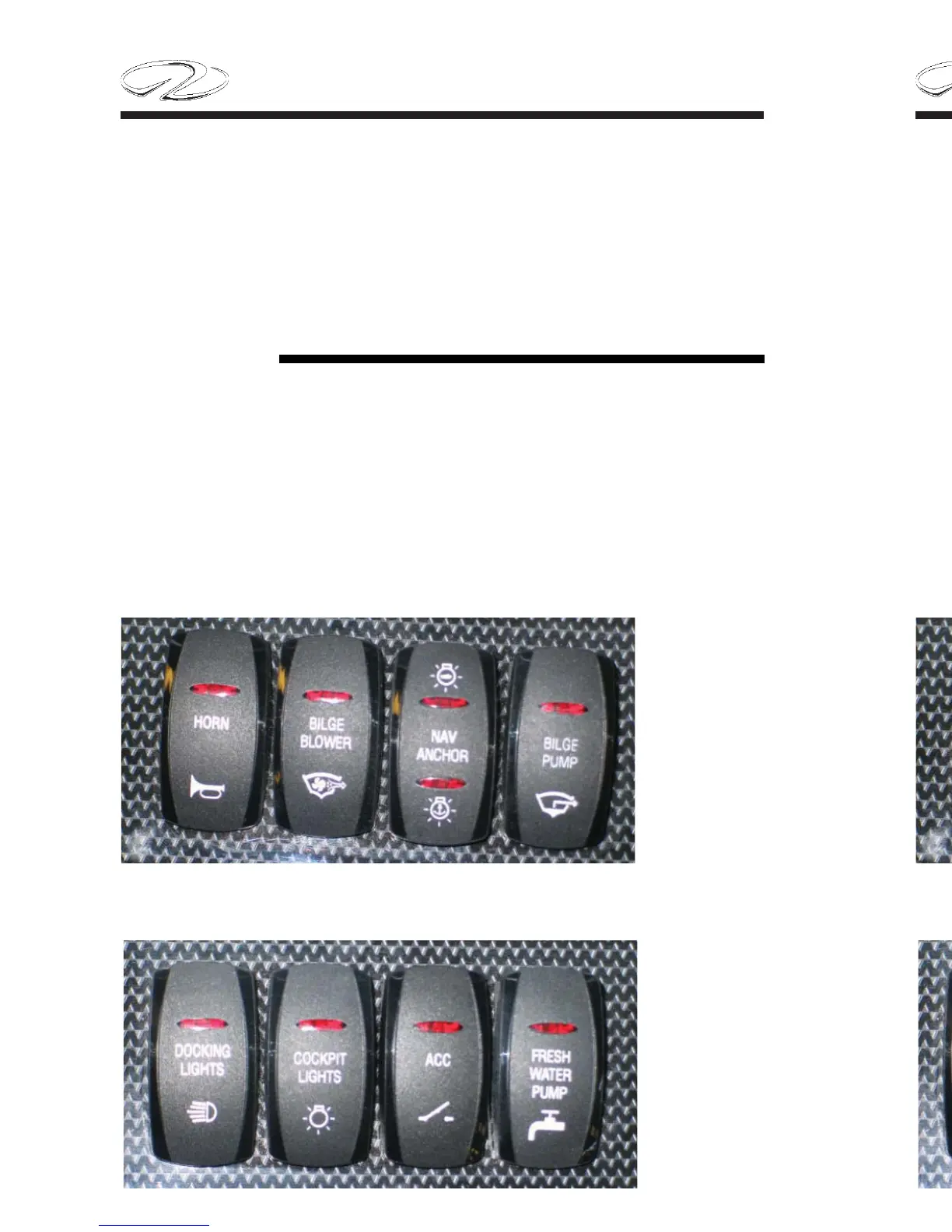
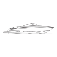
Following are the direct current switches used on your Regal boat. Your
boat may not use some of the switches mentioned because they represent optional
equipment not installed on your vessel. These switches are located on the
dash switch panel. Note: electrical components and specifi cations may
change at any time.
DC Switches
Typical Port Switch Panel
Typical Starboard Switch Panel
CHAPTER 4
4-4
The standard wire color, gauge size and function shown is used
throughout the marine industr
y. The charts are helpful in identifying
wire circuitry during troubleshooting or the adding of marine
accessories. Never replace a wire with a size other than shown in the
chart. This practice could result in fi re or component failure.
Following are the direct current switches used on your Regal boat. Your
boat may not use some of the switches mentioned because they represent optional
equipment not installed on your vessel. These switches are located on the
dash switch panel. Note: electrical components and specifi cations may
change at any time.
DC Switches
Typical Port Switch Panel
Typical Starboard Switch Panel