34
Chapter 4
TYPICAL BATTERY MANAGEMENT SYSTEM
The battery management system is an important ingredi-
ent of the yacht’s 12 volt direct current (DC) system. The
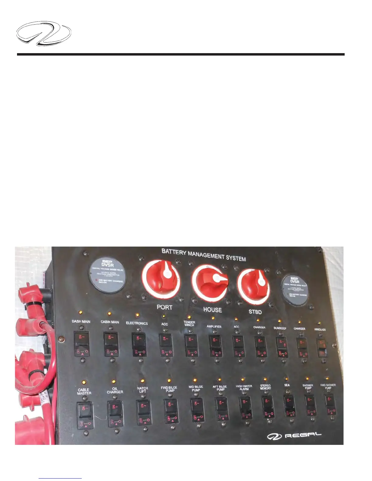
battery management panel consists of 3 universal battery
switches, 2 VSR’s and 2 banks of DC breakers plus the
wiring itself. Note the breaker sizes on the diagram below.
Should a replacement become necessary the breaker am-
perage is listed with each breaker.
In some cases the breaker protects a component; in other
cases it may also control a sub-panel or parts of a sub-
panel.
Note: The breakers can be reset. Use the procedure described in the
following pages.
The universal battery switch marked port is part of the
port engine cranking battery circuit. The universal battery
switch marked starboard is part of the starboard engine
battery circuit. Likewise, the switch marked house is part
of the “house” battery circuit. The port VSR is connected
to both the port cranking battery and the house battery.
The starboard VSR is connected to the starboard crank-
ing battery and the house battery.
 Loading...