38
Chapter 4
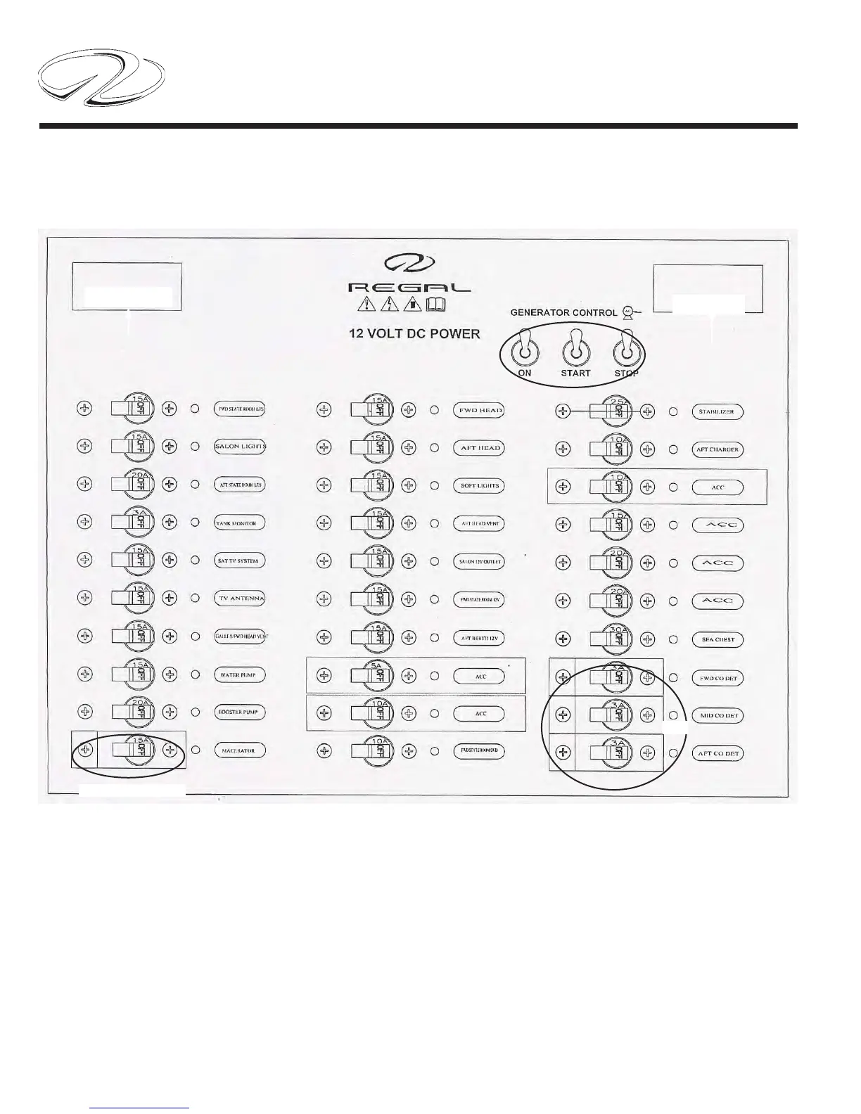
TYPICAL MAIN DC PANEL METER/SWITCH FUNCTIONS
The main DC control panel is located in the aft starboard salon behind the overhead cabinet doors. This panel is
protected by the cabin main breaker at the battery management center. The panel features an analog 12 volt DC volt
meter and amp meter to monitor electrical fl ow and current. These 2 instruments can be valuable aids in basic electri-
cal troubleshooting.
A triple Westerbeke generator switch cluster facilitates gen-set operations. A 3 amp in-line fuse located on the rear side
of the panel protects the blue soft indicator icon for each breaker. Notice the 3 CO and macerator covered breakers.
These switches require a 2 step operation to actuate the component. The cover must be lifted before the switch can
be activated. For more information read the sections on carbon monoxide and pumping waste overboard. Macerator
usage requires the same 2 step process.
DC VOLTS
DC AMPS
CO
MACERATOR
 Loading...