2418C JAN 00 1.5.5
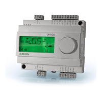
CORRIGO C10-LON
INSTRUCTION
Analogue 0...10 V DC control outputs, AO1, AO2,
AO3
Output signal 0...10 V DC, 5 mA. Short circuit proof.
AO1 Control output Y1
AO2 Control output Y2
AO3 Control output Y3
These outputs must refer to terminal 41, Signal neutral.
Since signal neutral in the Corrigo is galvanically
separated from system neutral the signal neutral from
the actuator must be connected to terminal 41 even if
the actuator and the Corrigo share a common trans-
former.
The function of the different outputs depends on the
configuration settings but the sequence order will always
be Y3 à Y2 à Y1 on increasing heat demand.
Other control outputs, DO1...DO7
The digital outputs DO1...DO6 are triac controlled.
0,5A, 24 V AC. Short term peak load 1A.
Output DO7 is a potential free relay contact.
The outputs are paired to 24 V AC supply inputs. (See
terminal schematics, page 6).
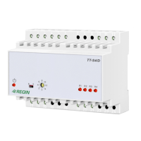
For higher voltages and currents use relay modules
RM6-24/D or RM6H-24/D that are specially designed for
use with Corrigo.
Some of the outputs have alternative functions
depending on the system configuration. This means for
example, that DX cooling cannot be combined with
control of two-speed fans.
DO1 Control supply air fan or supply air fan high speed
for two-speed fans.
DO2 Control exhaust air fan or exhaust air fan high
speed for two speed fans.
DO3 Control circulation pump or for electric heating
interlocking.
DO4 Control DX-chiller 1or supply air fan low speed for
two-speed fans.
DO5 Control DX-chiller 2 or exhaust air fan low speed for
two speed fans.
DO6 Ecternal frost protection or fire damper exercising.
(See text section DO6/DI6 page 6).
DO7 Potential free relay contact for alarm output.
1 A, 24 V AC/DC. Closes on alarm.
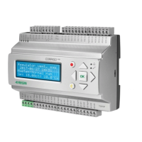
Buttons and display
Language
The menu text language can be changed.
Hold the ! button depressed during power up to enter the
setup mode. Then press ! again and a blinking marker will
appear next to the current language. Select the desired
language by using the arrow buttons. When the marker is
next to the desired language, press OK. Press OK again
to return to the normal menu system.
All information that can be shown on the display is
organised in menues in a ”menu-tree”.
Using the buttons on the front you can move between the
different menues in the tree, look at parameters, change
settings, display and reset alarms.
What you can see and do is governed by your log-on
level.
The ”Trunk” of the menu-tree contains the following
menues:
Logon
Configuration Only shown in level 3
Control temp ï Starting point
Running mode
AI Analogue in
DI Digital in
AO Analogue out
DO Digital out
Scheduler
Alarm settings Not shown in level 0
Settings Only shown in level 2 and 3
During normal running when the buttons are not in use a
series of menu pages is shown.
The display alternates between, a general display with
product description and clock, setpoint/actual tempera-
ture, and output status for the control outputs Y1, Y2, Y3.
To gain access to the menu-tree press OK and the
display will change to Control temp.
By pressing é and ê you can move up and down the
tree. The arrows to the right in the display indicate
whether there are menu pages above or below the one
shown.
>Temp control á
AI Analogue in â
To move out onto any of the ”branches” press OK. Out on
the branch you can then move about in the same way
using the arrowbuttons. By pressing Esc you can jump
back towards the trunk.
In menu pages with settable parameters you shift to
”Setting mode” by pressing !.
A dark blinking marker will then appear in the first settable
position. By using the arrow buttons the value can be
changed. When the correct value is shown press OK and
the marker will move to the next position. After OK on the
last position the new value is stored and the ”Setting
mode” is ended.
To abort without change press Esc and the marker will
move back to the previous position. Setting mode is
aborted automatically after a few minutes button-inactivity.
Shows the alarm queue. Displays active and non-
acknowleged alarms. The alarm-LED above the button is
lit when there are alarms in the queue.If there are multiple
alarms use the arrow buttons to move between pages.
Alarms are acknowleged by pressing OK.
To abort press Esc.
Login
Corrigo has 4 different login levels to prevent the user
from inadvertently changing any settings.
0 Without logging in most of the important parameters
can be viewed, alarms can be acknowleged but no
parameters can be changed.
1 Main setpoint, time and date can be set.
Outputs can be manually set and the running mode
can be set to manually on or off.
2 Gives access to most setpoints and running para-
meters.
3 Gives total access.
Used by the commissioning engineer for system
configuration.
Enables changing of login codes.
To login when the display shows the normal series of
information menues, first press OK and the display will
show Control temp.
Control Funct. á
>0 Suppl Air cnt â
INSTRUCTION 2
ð ð
*CORRIGO C10* Setpoint/Actual Y1 / Y2 / Y3
Mo 980907 10:10 20.0ºC / 20.0ºC 0% / 45% / 0%
 Loading...