108
2004 – 2014 Reliable Controls
®
Corporation. All rights reserved.
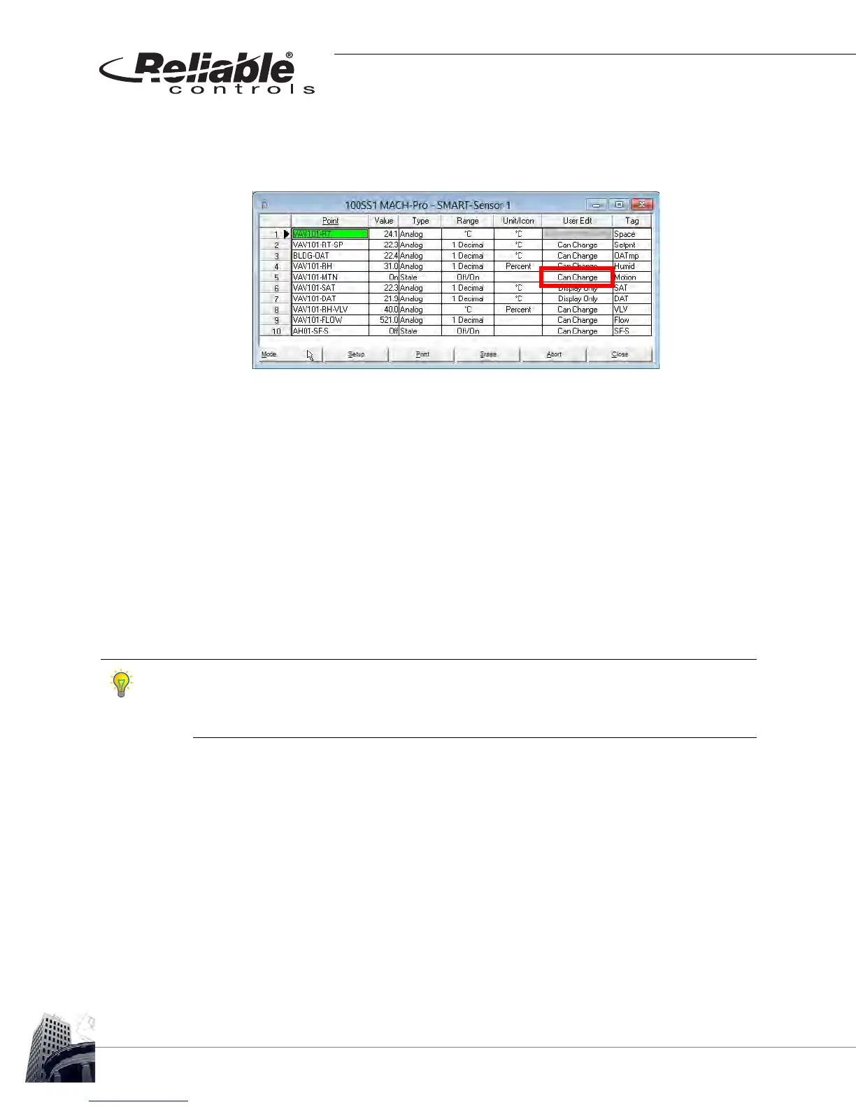
9 Decide which points should be modifiable from the SS-L and which points
should be configured for display purposes only. This is configured in the User
Edit column.
FIGURE 102: SS-L PROGRAMMING EXAMPLE - SMART-SENSOR WORKSHEET WITH USER EDIT CONFIGURED.
In Figure 102, note that the onboard motion sensor of the SS-L-H-OC is being
used. Notice that it is configured in Row 5 as required and that User Edit is
configured for Can Change. This is to permit the SS-L to change the value of the
mapped point.
Also notice that an icon has been selected for AH01-SF-S in Row 10. When the
mapped point is true (has a value of 1) the small fan icon will appear on the
default screen. When the mapped point is false (has a value of 0) the small fan
icon will disappear. Since this point is configured for Display Only, the value will
only be displayed as an icon and will not appear to a user scrolling through the
LCD.
If the User Edit column in the SMART-Sensor worksheet is set to a value of Can Change, an
SS-L can set the value of a point by one of three methods; 1) user-entry via the operator
interface, 2) input sensors, and 3) control of onboard outputs. If the User Edit column is set
to a value of Display Only, then the SS-L cannot change the value of a point.
 Loading...