IN-7000
7
2. INSTALLATION
2.1. Unpacking
2.1.1. Chair
2.1.1.1. Cut the shipping bands, open the top of the
shipping carton, and remove all packing material and boxes
that can be easily reached. Remove (4) nuts and remove
both base clamping boards.
2.1.1.2. It is recommended that the skid be positioned as
close as possible to the desired chair location.
2.1.1.3. Remove at least two small shipping blocks stapled
to the top of the skid. The chair can now be slid and/or
tipped from the skid onto the oor.
2.1.1.4. Do not lift the chair by the upper structure.
However, the chair may be tipped or slid into position by
pushing or pulling on the upper structure.
2.1.1.5. With the chair in position, remove all remaining
paper pads, plastic, tape, strings, etc.
2.2. Assembly
2.2.1. Headrest
2.2.1.1. Remove the headrest from its carton, and mount
it into position onto the chair back. Using the proper hex
key wrench, tighten the cap screw to clamp the headrest
securely into its mounting bracket.
2.2.2. Power Receptacle
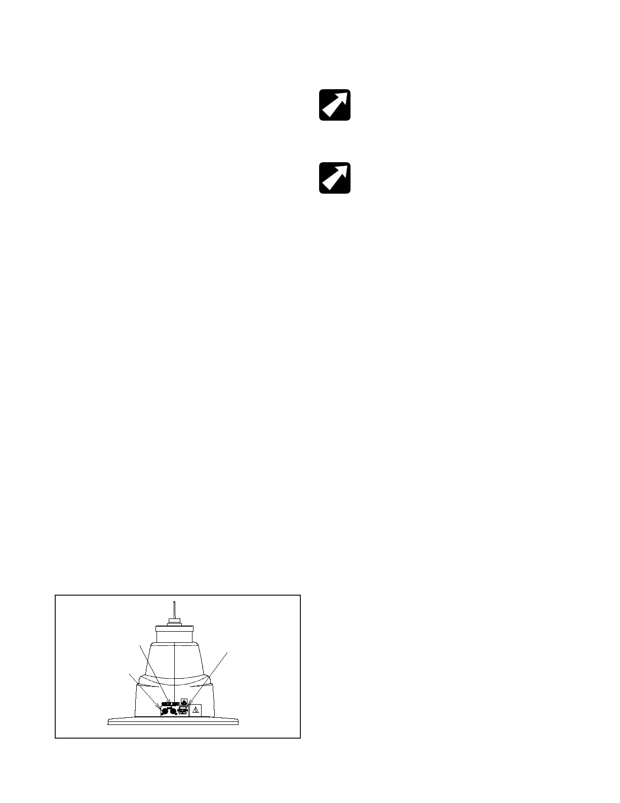
2.2.2.1. Locate the footswitch assembly, chair control
cable, and the power cord assembly. Refer to gure 1 for
receptacle location and attach all cables.
2.2.2.2. To disconnect power to Chair unplug power cord
from Instrument Stand or from wall receptacle.
NOTE: If this chair is purchased in conjunction
with a Reliance® instrument stand, the chair control
cable supplied will provide proper operation. Refer
to the instrument stand manual for connection to
the stand.
REMARQUE : Si cette chaise est achetée avec
un support à instruments Reliance®, le câble
de commande de la chaise fourni permettra un
fonctionnement adéquat. Se référer au manuel du
support d’instrument pour savoir comment faire la
connexion au support.
2.2.3. Setting Rotation Stop
2.2.3.1. When used in an ophthalmic or optometric
environment, the rotation of the chair top is manufactured
for a right-handed examination position (delivery system
positioned on the patient’s left). If you wish to position the
oor unit for a left handed examination position, the rotation
stop in the chair should be altered.
2.2.3.2. Separate the skirt hanging from the upholstered
chair back connected to the upholstered seat by pulling
upward on each end of the skirt until the Velcro fasteners
are separated. Remove the screw located under the chair
top and the front edge of the center of the chair. Lift upward
on the seat and remove.
2.2.3.3. Standing in front of the chair locate the hole in
the seat board positioned to the lower right of the center
circle. Using a 1/2” socket, remove the bolt located in the
circle, and install in the threaded hole located in the lower
left of the center circle.
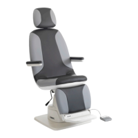
FIGURE 1
BASE
Power Cord &
Fusedrawer
Footswitch
Cable
Chair Control
Cable