Section S
Contents
Description
Operation 1 Heater unit - removal & replacement
Operation 2 Blower unit - removal & replacement
Heater
Description
The heater is of the fresh air type and is mounted behind the centre
console on the engine bulkhead. Water from the cooling system is fed
to the heater via hoses from the engine. Fresh air is drawn from the
front of the vehicle and ducted to the heater. The heated air is forced
through vents in the foot wells and via hoses to the demisters.
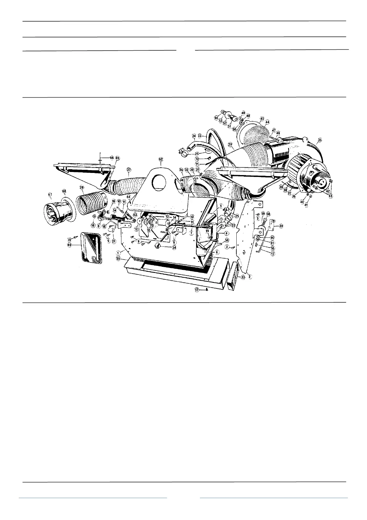
Figure 1 Heater system - exploded view
1. Heater casing assembly 25. Clip 49. Nut
2. Side cover assembly 26. Air hose demist RH 50. Rubber mounting nut
3. Screw 27. Air hose demist LH 51. Rubber mounting
4. Radiator and seals 28. Air hose fascia 52. Coach washer
5. Air mixing valve and seal 29. Air hose ram 53. Spring washer
6. Distribution valve and seal 30. Flange pipe 54. Nut
7. Lever and spindle RH 31. Screw 55. Air distribution box
8. Lever and spindle LH 32. Clip 56. Seal
9. Screw 33. Air vent RH 57. Screw
10. Plunger 34. Heater control knob 58. Screw
11. Spring 35. Blower halves 59. Coach washer
12. Spacer 36. Blower and mounting plate 60. Washer
13. Friction disc 37. Rotor 61. Nut
14. Shake proof washer 38. Screw 62. Air chamber
15. Spring washer 39. Washer 63. Air chamber seal
16. Spire clip 40. Shake proof washer 64. Screw
17. Link rod RH 41. Nut 65. Demister
18. Link rod LH 42. Washer 66. Rivet
19. Star lock washer 43. Nut 67. Fascia air vent nozzle
20. Distribution valve lever 44. Air intake mesh 68. Retaining ring
21. Air blend valve lever 45. Inlet extension 69. Escutcheon
22. Sponge washer 46. Screw 70. Screw
23. Water hose 47. Washer 71. Strap
24 Water hose 48. Shake proof washer 72. Stud
 Loading...
