Page 18
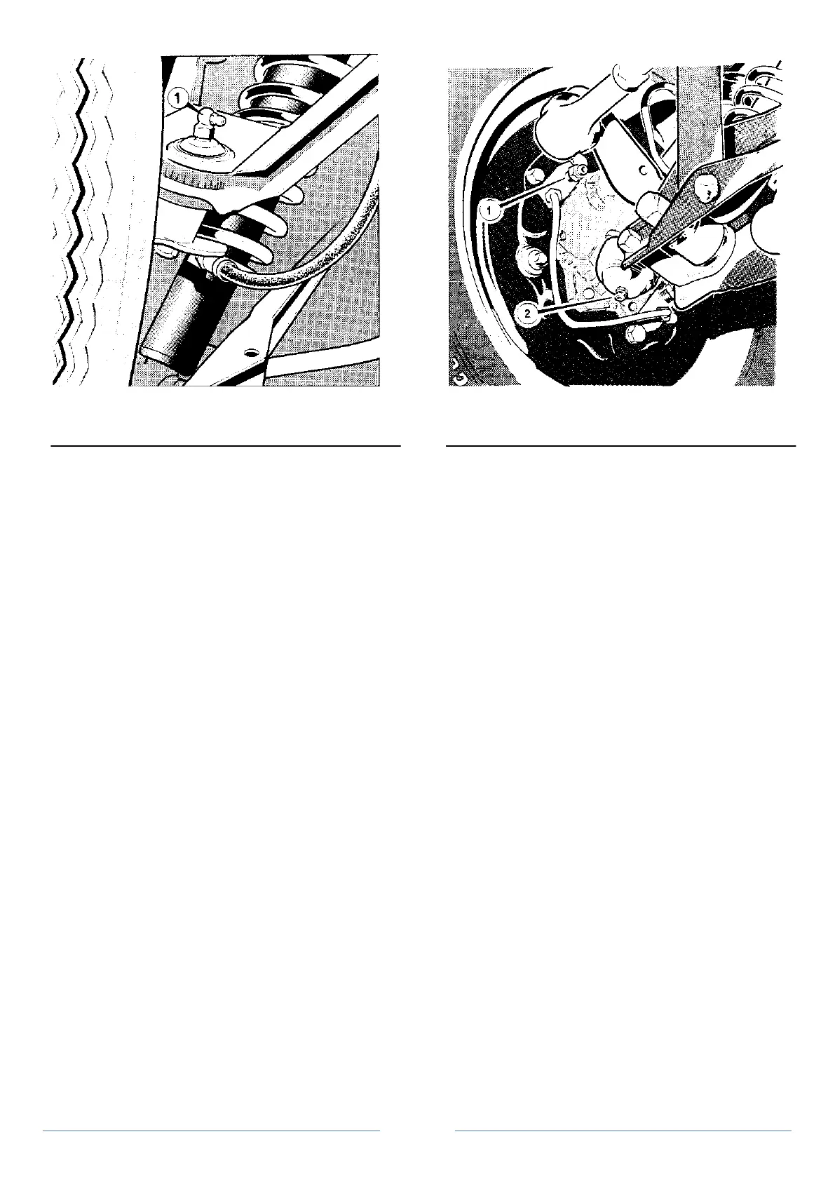
Figure 2 Upper wishbone ball
joint lubricator
1. Ball joint - grease nipple
Operation 4 Upper ball joint - removal and replacement
To remove (figure 1)
1. Place vehicle on ramp or support on suitable chassis stands.
2. Remove road wheel.
3. Disconnect the hydraulic brake flexible hose from the
bundy pipe at the support bracket and plug to prevent fluid leakage or
dirt ingress.
4. Remove the nut securing upper ball joint to vertical link,
releasing the brake pipe support bracket.
5. Using a suitable ball joint splitter, release the ball joint
taper from the vertical link.
6. Remove the bolts and nuts securing the upper wishbone
pivots and remove the wishbone complete with upper ball joint.
Note: If the wishbone bolts cannot be withdrawn because of the
damper, the wishbone pivot brackets can be removed by releasing the
nyloc nuts securing the brackets to the frame.
7. Remove the external circlip securing the ball joint to the
wishbone and prise or press the ball joint from the mounting plate in
the wishbone assembly.
Reassemble in reverse order.
Operation 5 Lower ball joint and pivot bracket - removal
and replacement
To remove (figure 1)
1. Place vehicle on ramp or support on suitable chassis stands.
2. Remove road wheel.
3. Remove bolt, nut and spacer securing damper bottom bush
to lower wishbone.
4. Remove bolt and nut securing the lower ball joint pivot
bracket assembly to the lower wishbone.
5. Remove the split pin from the castellated nut securing the
lower ball joint to the vertical link.
6. Remove the castellated nut.
7. Release the taper on the shank of the ball joint from the
vertical link and remove the ball joint and pivot bracket assembly.
replace in the reverse order, tightening the castellated nut to 4.29 to
4.98 kb/m (31 to 36 lb/ft) and renewing the split pin.
Figure 3 Lower fulcrum - lubricator
1. Bleed screw
2. Lower fulcrum - grease nipple
Operation 6 Upper wishbone - bush replacement
To remove (figure 1)
1. Dismantle upper wishbone assembly as sequence 1-5 of
operation 4.
2. Press out the wishbone bushes.
3. Press in the new bushes ensuring that they are centred in
the wishbone.
4. Refit the wishbone as in operation 4. Check camber setting
see Section D
Operation 7 Lower wishbone and strut - bush replacement
To remove (figure 1)
1. Place vehicle on ramp or support on suitable chassis stands.
2. Remove road wheel.
3. Remove nut, spacer and bolt securing strut to lower
wishbone.
4. Remove nut and bolt securing strut to bracket on frame.
5. Remove nut, spacer and bolt securing bottom of damper to
lower wishbone.
6. Remove nut and bolt securing lower wishbone to lower ball
joint pivot bracket.
7. Remove bolt, lock washer and nut plate securing lower
wishbone to frame. Press out the bushes from strut and lower
wishbone and replace bushes ensuring new bushes are centred
correctly.
reassemble in reverse order. Check tracking and camber settings see
Section D.
Operation 8 Vertical link - removal and replacement
1. Place vehicle on ramp or support on suitable chassis stands.
2. Remove road wheel.
3. Remove nut from track rod end ball joint and disconnect
the ball joint from the steering arm.
4. Disconnect the hydraulic brake flexible hose from the
bundy pipe at the support bracket and plug to prevent fluid leakage or
dirt ingress.
5. Remove bolt, nut and spacer securing damper bottom fixing
to lower wishbone.