Page 37
Figure 3 Centralising the clutch
Refitting
1. Heat up the new ring gear uniformly to a temperature of
200°C.
2. Place the flywheel on a stable flat surface, clutch face
uppermost and clean the ring gear locating surface.
3. Slip the heated new ring gear in to place and hold in
position until it contracts under cooling sufficiently to grip the
flywheel.
4. Allow the assembly to fully cool naturally to avoid
distortion.
Refitting the flywheel assembly
1. Clean the mating face between the flywheel and the end of
the crankshaft. Check that the locating dowel is undamaged and
ensure that the spigot bush is in place. Check the bush for wear. If
wear is evident then knock the old one out and fit a new one using
special tool no. RT 7485 (Figure 2). Needle roller bearings have been
used as an alternative to the phosphor bronze bush and care must be
taken when replacing these. It is vital to note that the hardened
square end face of the bearing must face the tool used to press in the
bearing. Use of the rolled end of the bearing will distort the shell and
damage the rollers. In many cases the part number or makers name
will be stamped in to the hardened end to aid identification. If this
does not apply, great care must be observed to identify the correct
end.
2. Fit the flywheel to the crankshaft locating it over the dowel.
3. Secure the flywheel with three set screws and a new tab
washer tightening to a torque of 4.03 kg/m (29 lb/ft). The tabs on the
washer should be bent over to secure the set screws.
4. Check the flywheel for alignment using a dial indicator
gauge. A 0.08 to 0.13 mm (0.003 to 0.005 in) run out is acceptable. If
this is exceeded the flywheel needs to be renewed.
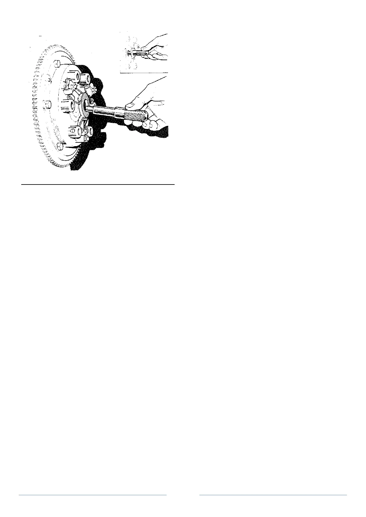
5. Using special tool no. RT 7485 as a centraliser, or if this is
not available an input shaft from a spare gearbox, replace the clutch
disc and pressure plate assembly on to the flywheel, securing evenly
with six set screws and lock washers to a torque of 1.66 to 2.07 kg/m
(12 to 15 lb/ft) see Figure 3. The pressure plate assembly should be
tapped with a hide mallet to ensure it is square on the flywheel.
6. Check clutch run-out does not exceed 0.381 mm (0.015 in)
on the steel thrust disc.
7. Refit the gearbox.
Operation 3 Sump removal and replacement
1. Drain engine oil.
2. Undo the 15 set screws and remove the spacers, lock
washers, sump and gasket.
3. Clean the sump and the cylinder block facing.
4. To eliminate possible oil linkage, the two centre front and
rear sump fixing screws should be thoroughly cleaned, then
generously coated with "Hylomar" sealant before refitting.
5. Fit new gasket, replace sump and tighten the 15 set screws,
spacers and lock washers evenly.
Figure 4 Engine, cylinder block -
exploded (page 38)
1. Cylinder block 21. Tube, dipstick 41. Spring 61. Washer
2. Stud, cylinder head 22. Mounting plate 42. Ball 62. Gasket
3. Stud 23. Gasket 43. Insert 63. Set screw
4. Stud 24. Stud, plate to block 44. Mounting plate 64. Lock washer
5. Stud 25. Nut, plate to block 45. Dowel 65. Washer
6. Stud, water pump 26. Lock washer 46. Dowel 66. Nut
7. Stud, alternator strap 27. Cover, timing chain 47. Set screw 67. Washer
8. Stud, fuel pump 28 Gasket 48. Set screw 68. Nut
9. Stud, bearing housing cap 29. Oil seal, cover 49. Washer 69. Lock washer
10. Washer 30. Bolt 50. Lock washer 70. Restrictor cup
11. Nut 31. Bolt 51. Rear oil seal 71. Mounting rubber
12. Core plug, camshaft 32. Bolt 52. Rear cover 72. Washer
13. Bridge piece front 33. Lock washer 53. Gasket 73. Nut
14. Bridge piece rear 34. Nut 54. Set screw
15. Packing, bridge piece 35. Oil filter 55. Set screw
16. Screw 36. Oil filter adapter 56. Washer
17. Cylinder liner 37. Plug 57. Lock washer
18. Plug, water drain 38. Oil pressure switch 58. Dowel
19. Washer, plug 39. Oil pressure valve retainer 59. Sump
20. Dipstick 40. Washer 60. Sump drain plug
 Loading...
