Page 59
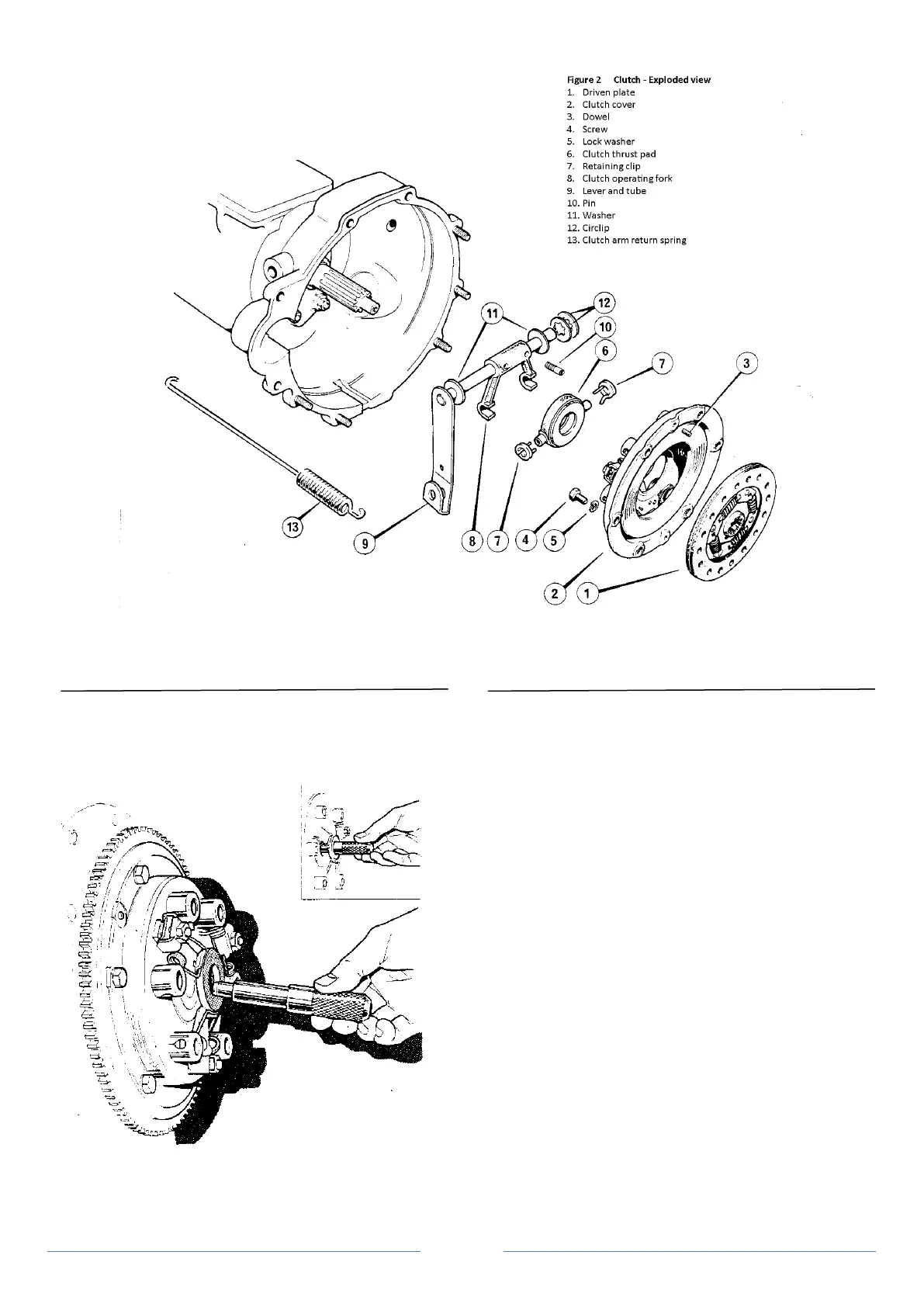
Figure 3 Centralising the clutch
Tap the pressure plate assembly with a hide mallet to ensure it is
correctly seated on the flywheel.
2. Check the clutch run-out does not exceed 0.381 mm
(0.015 in) on the steel thrust disc.
Operation 3 Clutch operating fork, lever and thrust pad
Removal and replacement
The operating fork is pinned into position on the shaft of the clutch
lever and tube assembly which is pivoted through the top of the
gearbox bell housing. To ensure that the thrust pad moved in the
correct plane it is pivoted in the operating fork and held firm by lock
springs. (Figure 2)
To remove
1. \\remove gearbox (Section G).
2. Using a screwdriver, prise off the locking washers and plain
washer, securing the clutch lever shaft to the bell housing.
3. Tap out the two clutch fork retaining mills pins with a 3.175
mm (0.125 in) diameter drift.
Note: It is advantageous to first remove the right-hand pin to facilitate
easier withdrawal.
4. Withdraw the clutch lever and shaft assembly from the
gearbox bell housing and remove the clutch fork.