Page 61
(b) Drilling out the fixing holes in the bracket and securing it
with two No.10 set screws, nuts and lock washers.
Note: If the fixing holes in the body have been enlarged excessively it
is advisable to use method (b).
2. Clean all traces of sealing compound from the abutment
bracket under the foot well
3. Smear a coating of "I.C.I. Silcoset 152" sealing compound on
the seating face of the new clutch cable abutment bracket.
4. Push the clevis end of the new clutch cable assembly
through the hole in the foot well, locate the abutment bracket and
secure to the body using either method detailed above.
5. From inside the vehicle foot well connect the clutch cable
clevis to the pedal lever with the clevis pin and fit the washer and a
new split pin.
6. Underneath the vehicle insert the threaded end of the cable
through the trunnion and fit the adjuster nut.
7. Adjust the clutch (see Operation 1)
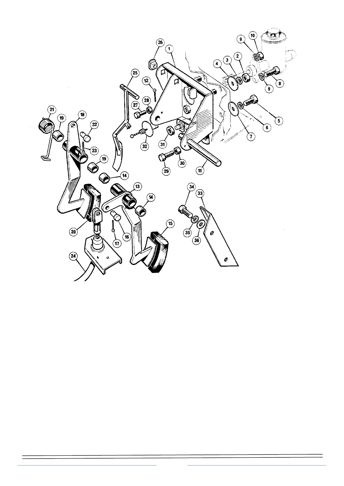
Figure 4 Pedal bracket assembly - exploded view
1. Pedal mounting bracket 13. Clutch pedal assembly 25. Throttle pedal
2. Nut 14. Clutch pedal pivot bush 26. Throttle pedal pivot moulding
3. Lock washer 15. Pedal rubber 27. Adjuster bolt
4. Coach washer 16. Clevis pin 28. Lock nut
5. Bolt 17. Split pin 29. Adjusting bolt
6. Lock washer 18. Brake pedal assembly 30. Lock nut
7. Coach washer 19. Brake pedal pivot bush 31. Lock nut, brake light switch
8. Bolt 20. Pedal rubber 32. Accelerator pedal assembly
9. Lock washer 21. Brake pedal return spring 33. Clutch footrest bracket
10. Nut 22. Clevis pin 34. Bolt
11. Pivot shaft 23. Split pin 35. Lock washer
12. Split pin 24. Clutch cable 36. Washer