Page 70
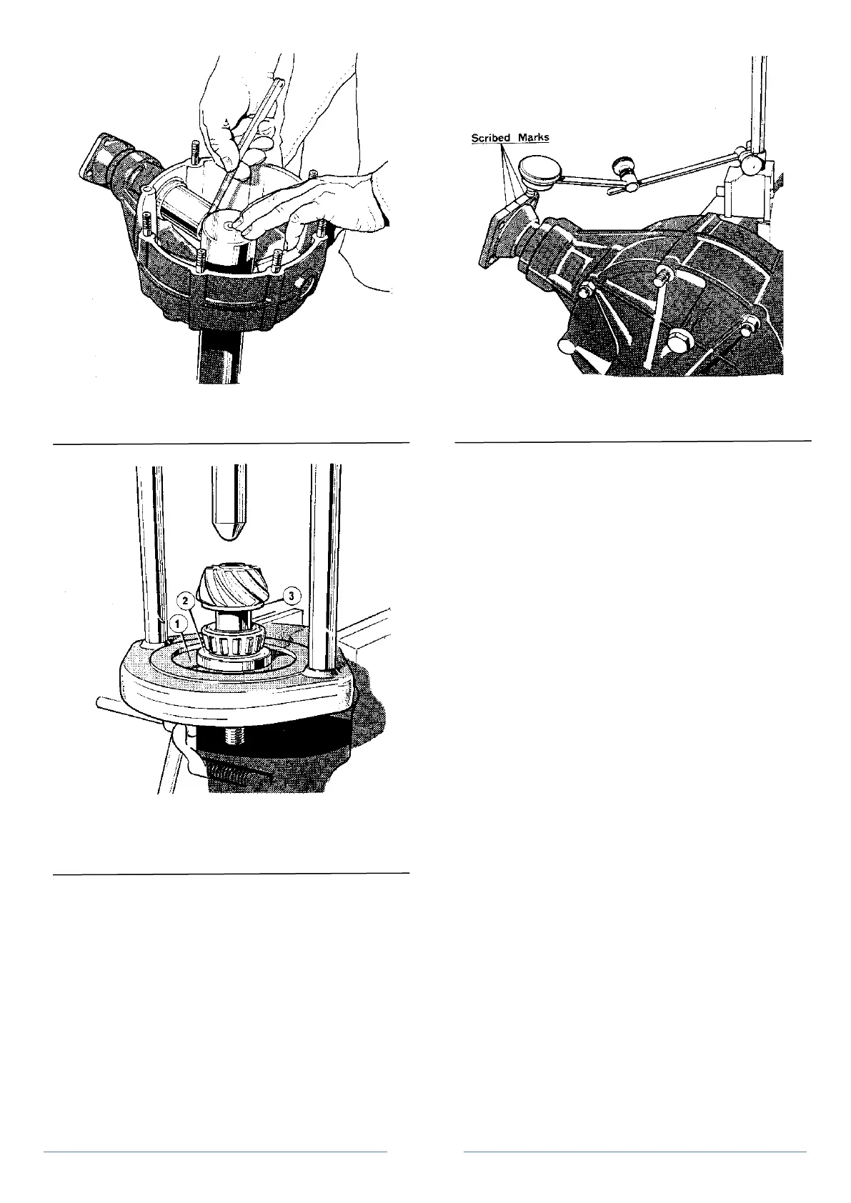
Figure 12 Determining pinion mounting distance using dummy
pinion
Figure 13 Replacing pinion bearing cone using hand press and collars
1. Collars
2. Adaptor
3. Spacing washer
pinion shank, this means it has been manufactured high and requires
reducing in height by the same distance. Therefore if the gap
measured is, say 0.044, the spacers required will be 0.44 minus 0.030
minus 0.003 which will equal spacers to the value of 0.011 thicker
than that used for measurement.
5. Remove the dummy pinion assembly, place the selected
spacer on the pinion and assemble the bearing cone, using the hand
press tool No. 47, adapter RT 8765/2 and bearing replacer collars RT
8765/1 (Figure 13)
Operation 6 Re-assembly - installation of pinion in axle case
1. Add the collapsible spacer to the pinion assembly and place
the new oil seal in the pinion housing. Place the pinion assembly in the
pinion housing and replace the pinion flange and the nyloc nut.
Figure 14 Determining pinion to crown wheel backlash using a
dial gauge
2. Using a torque wrench, progressively collapse the spacer
starting at 6.91 kg/m (50 lb/ft). Preload begins when end float is
eliminated at approximately 11.06 kg/m (80 lb/ft).
3. Turn the pinion to ensure that the pinion rollers are
correctly seated.
4. Using a torque meter, check the torque required to turn the
pinion nut. This should be set at 0.150 to 0.184 kg/m (13 to 16 lb/in).
Operation 7 Re-assembly - determining the correct backlash,
crown wheel to pinion
1. Replace the differential assembly complete with the
dummy bearings into the differential housing and secure the two
halves of the axle case together.
2. If removed, refit the push rods of tool No. RT8732 as for
setting the differential end float. Slacken the right-hand side and then
screw in the left-hand push rod as before, using a torque wrench set
to 0.28 to 0.55 kg/m (2 to 4 lb/ft) maximum. This will give minimum
backlash. Screw up the gauging nut lightly to the face of the disc and
lock in position with the lock nut as before.
3. Unscrew the left-hand side and screw in the right-hand side
until the correct backlash is obtained. This should be checked at the
pinion flange as follows:
Setting the correct backlash, pinion to crown wheel, using a dial
gauge
1. With pinion flange horizontal, scribe a centre line on the
top end of the flange and a line 7/8 in on either side of it. (Figure 14).
This represents the overall diameter of the pinion.
2. Set up a dial gauge indicator on a magnetic base as shown
in Figure 14.
3. Using a screwdriver through the level/filler aperture, lock
the crown wheel by wedging it in between the pinion flange and the
bolt heads.
4. Rock the pinion flange and read off the backlash readings.
This should measure 0.006 to 0.008 in.
5. Screw in the left-hand side until a stop is felt, screw up
right-hand side until contact is made. Measure minimum backlash.
Unscrew left-hand rod and tighten right-hand rod at approximately
half turn intervals until the correct backlash is obtained.