Page 72
Section L
Contents
Description
Routine maintenance and adjustments
Operation 1 Check front brake lining and adjustment
Operation 2 Check rear brake lining and adjustment
Operation 3 Handbrake adjustment
Handbrake cable lubrication
The hydraulic system
Operation 4 Bleeding the hydraulic system
Operation 5 Front brakes - fitting new shoes
Operation 6 Front wheel cylinders - removal & replacement
Operation 7 Rear brakes - fitting new shoes
Operation 8 Rear wheel cylinders - removal & replacement
Operation 9 Master cylinder - removal & replacement
Brake pedal assembly
Operation 10 Handbrake cable - replacement
Operation 11 Handbrake lever - removal & replacement
Dual circuit braking system
Description
The hydraulic braking system operates drum brakes at both front and
rear. A mechanical handbrake linkage is provided, operating on the
rear brakes only. The brake pedal, connected directly to the master
cylinder via a short push rod, also incorporates a stop light switch
mounted on the pedal bracket assembly.
Routine maintenance and adjustments
Check the level of the brake master cylinder weekly and top-up if
necessary.
Every 6,000 miles (10,000 km)
Adjust brakes.
Check and grease handbrake cable.
Check, bleed if necessary and top up the hydraulic system.
Inspect the hydraulic system for leaks and chafing.
Every 36,000 miles (60,000 km)
Replace fluid, renew seals or replace units, replace hoses.
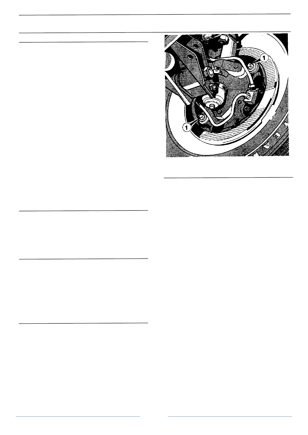
Operation 1 Check front brake lining and adjustment
A manual eccentric pin type brake adjuster is fitted to both brake
shoes (Figure 1).
1. Check brake drums are cold.
2. Jack up the vehicle until the front wheel is clear of the
ground.
]
Brakes
Front brake adjusters
1. Adjuster
3. Remove the road wheel and fully slacken off the brake
adjusters.
4. Remove the front brake drum.
5. Check the lining material thickness. Linings that are bonded
to the shoes must not be allowed to wear below 1.5 mm (1/16 in) in
thickness. Riveted linings should be changed when the material wears
within 0.75 mm (1/32 in) of the rivet heads.
6. If the linings are serviceable refit the brake drum, locating
the larger stud hole over the stud with a collar on it (this is to preserve
the balance of the hub/drum assembly).
7. Replace the road wheel and adjust as follows: Turn the
adjuster of one shoe to bring the lining away from the shoe (in the
opposite direction to wheel rotation). Turn the other adjuster in the
direction of wheel rotation until the drum is locked. Then slacken back
until the wheel is sufficiently free to rotate without binding.
8. Rotate the other adjuster in the direction of wheel rotation
until the drum is locked. Again back off until the wheel is just
sufficiently free to turn without binding.
Note: This minimum adjustment must be performed accurately to
obtain the minimum clearance between the shoe linings and drum,
with consequent minimum pedal travel.
Repeat with the opposite wheel.
Operation 2 Check rear brake lining and adjustment
1. Jack up the vehicle until one rear wheel is clear of the
ground.
2. Check the linings as described for the front wheel.
3. If the linings are serviceable, replace the drum and road
wheel and adjust as follows:
Release the handbrake and whilst rotating the wheel, turn the
adjuster (Figure 2) clockwise until the shoes touch the drum. Continue
"one click" at a time until the drum is locked. Slacken the adjuster
"two clicks" when the wheel should rotate freely. repeat with the
other wheel.