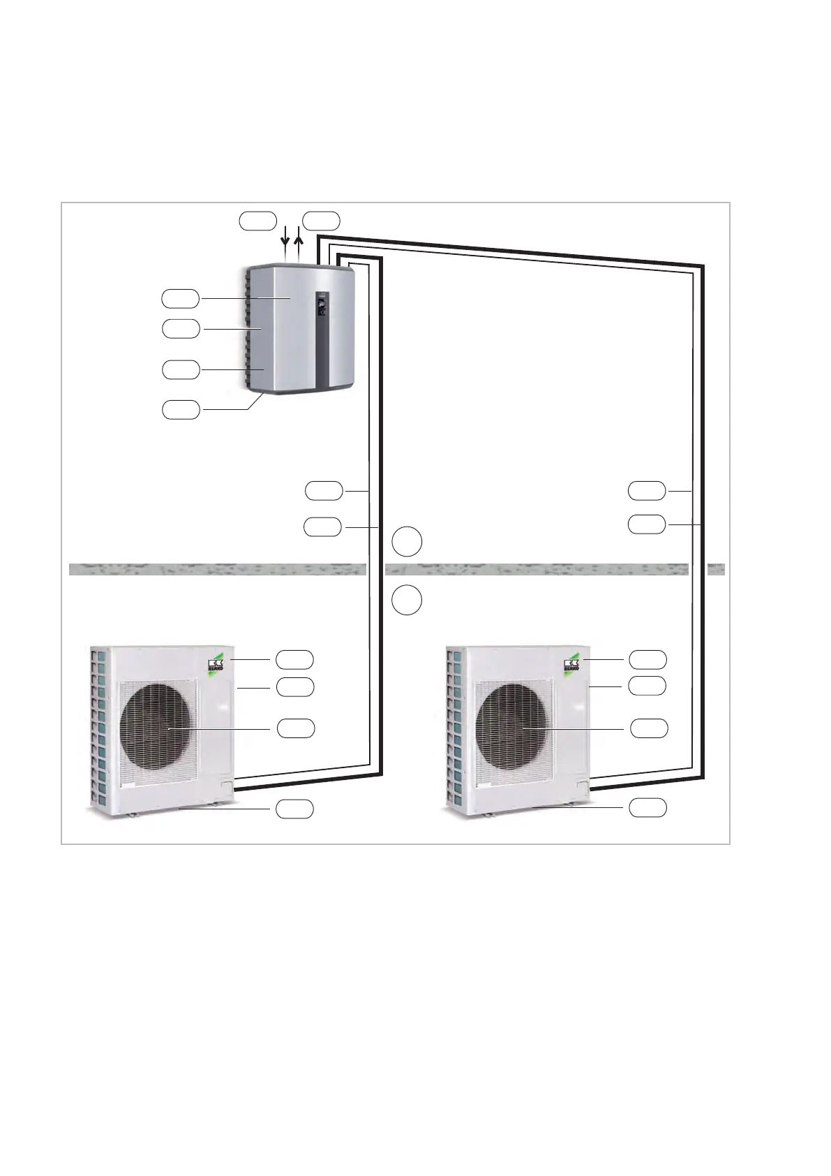
3 Electrical wiring WKF 120/180 Duo
3.1 System layout WKF 120 Duo
IB
AB
NAM
KA1
STL
KML
AM1
VEN
STL
KML
IM
NIM
NZH
KA2
VHZ
AM2
VEN
KA1
NAM
GRL
Fig. 13: System layout WKF 120 Duo
AB: Outdoor area
IB: Indoor area
AM1,2: Outdoor module WKF 120 Duo
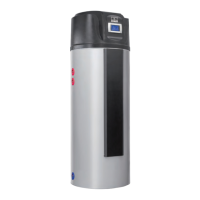
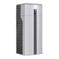
IM: Indoor module WKF 120 Duo
GRL: Common return pipe
KA1: Condensate drain, OM (must be designed to
be frost proof!)
KA2: Condensate drain, IM
KML:
Refrigerant piping
3
/
8
" and
5
/
8
"
NAM: Power supply, OM = 230V / 1~ / 50Hz
20A (e.g. 3x2.5 mm
2
)
NIM: Power supply, IM = 230V / 1~ / 50Hz
16A (e.g. 3x1.5 mm
2
)
NZH: Power supply for auxiliary heater (optional),
(e.g. 5x2.5 mm
2
)
STL:
Control line sheathed (e.g. 2x1 mm
2
)
VEN: Fan
VHZ: Inlet for heating
REMKO WKF series
26
 Loading...