2 Electrical wiring WKF/WKF-compact 70/120/180
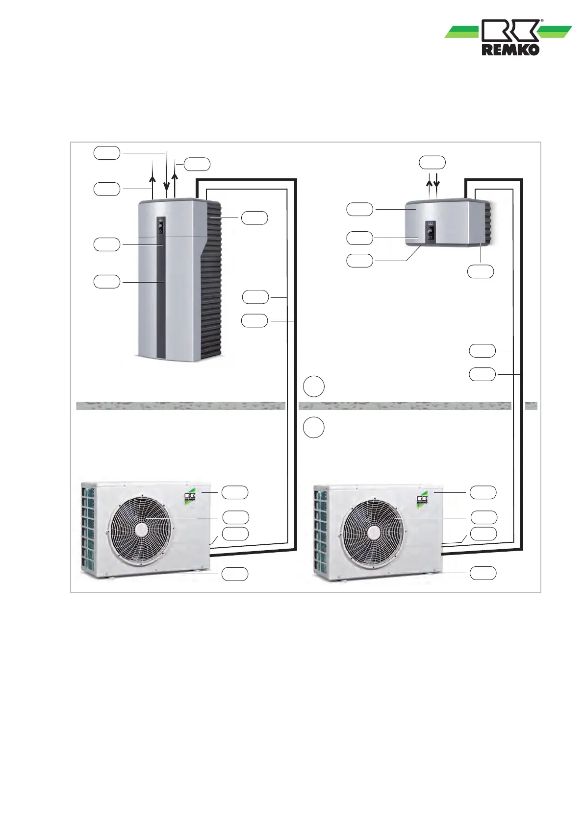
2.1 System layout WKF/WKF-compact 70
IB
AB
IM1
NAM
KA1
STL
KML
NIM
NZ1
VWW
GRL
VHZ
AM1
VEN
STL
KML
IM2
NIM
NZ2
KA2
VRH
NAM
AM2
VEN
KA1
Fig. 1: System layout WKF/WKF-compact 70
AB: Outdoor area
IB: Indoor area
AM1,2: Outdoor module WKF-compact 70, WKF 70
IM1,2: Indoor module WKF-compact 70, WKF 70
GRL: Common return pipe (DN 25)
KA1: Condensate drain OM (must be designed to
be frost proof!)
KA2: Condensate drain IM
KML:
Refrigerant lines
3
/
8
" and
5
/
8
“
NAM: Mains supply OM = 230V / 1~ / 50Hz
16 A (e.g. 3x1,5
mm
2
)
NIM: Mains supply IM = 230V / 1~ / 50Hz
10A (e.g. 3x1,5 mm
2
)
NZ1: Mains cable electric auxiliary heater (e.g.
5x2,5 mm
2
)
NZ2: Mains cable electric auxiliary heater
(optional), (e.g. 5x2,5 mm
2
)
STL:
Control cable sheathed (e.g. 2x1mm
2
)
VEN: Fan
VHZ: Inlet for heating (DN 32)
VRH: Hot-water inlet and return pipes (DN 32)
VWW: Inlet pipe for hot-water storage (DN 32)
7
 Loading...