20
Fitting
Proceed in the reverse arder
of
remaval.
Dashboard
o
Stripping
-
Rigging
Replacement
of
instrument
panel
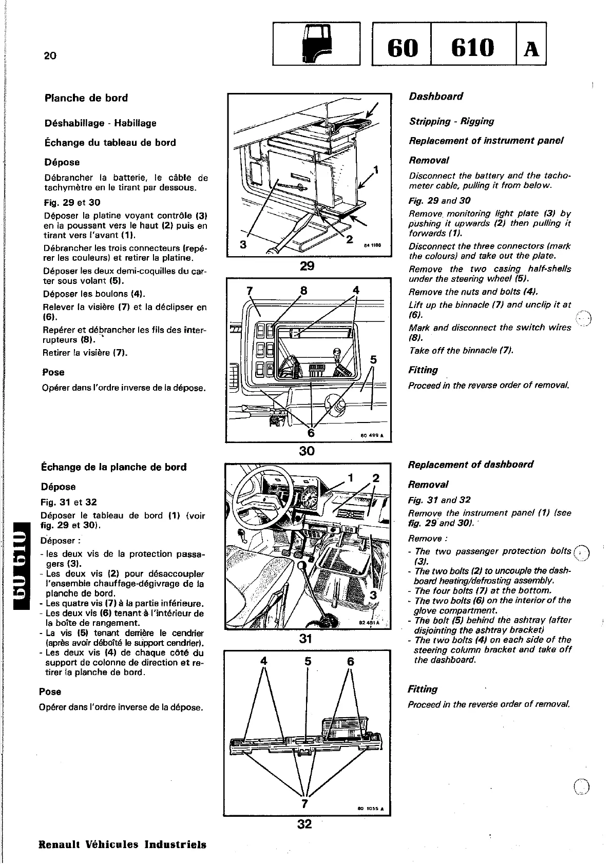
Removal
Disconnect the battery and
the
tachD~
meter
cable, pulling
if
trom
below.
Fig.
29
and
30
Remove.
monitoring
Hght
plate
13)
by
piJshing
it
upwards
(2)
then
pulling
it
forwards
11).
Disconnect the three connectors (mark
the
c%urs)
and take
out
the
plate.
Remove the
two
cas;ng
half-shells
under
the steering wheel151.
Remove the
nuts
and
bolts
141.
Lift
up
the
binnacle
(7)
and
unclip
if
at
161.
Mark and disconnect the
switch
wires
181.
Take
off
the binnacle (7).
Removal
Fig.
31
and
32
Remove the instrument panel
(1)
(see
fig.
29
and
30)
..
Remove:
-
The
two
passenger protection bolls
(.').
13}.
'
- The
two
bolts 12/ ta uneouple the dash-
board heating/defrosting assembly.
- The
four
bolts
17}
at
the
bottom.
- The
two
bolts
16}
on
the
interior
of
the
y/ove
compartment.
- The
boit
15}
behind
the
ashtray
lafter
disjointing
the
ashrray braeket)
- The
two
bolts
14/
on
each
side
of
the
steering column bracket and take
off
the
dashboard.
Replaeemen1
of
dashboard
Fitting
Proceed in the reverSe arder
of
remaval.
65
4
Planche
de
bord
Pose
Opérer dans l'ordre inverse de
la
dépose.
Déshabillage
-
Habillage
Échange
du
tableau
de
bord
Dépose
Débrancher la batterie, le câble de
tachymètre
en
le
tirant
par dessous.
Fig.
29
et
30
Déposer la platine voyant contrôle
131
en
la
poussant
vers
le
haut
{2}
puis
en
tirant
vers
l'avant
(1).
Débrancher les trois connecteurs (repé-
rer les couleurs)
et
retirer
la
platine.
Déposer les deux demi-coquilles
du
car-
ter
sous
volant
(5).
Déposer les boulons
(4).
Relever la visière {7}
et
la
déclipser
en
(6).
Repérer
et
débrancher les
fils
des
inter-
rupteurs
(8)
..
,
Retirer
la
visière (7).
Échange
de
la
planche
de
bord
Dépose
Fig.
31
et
32
Déposer le tableau
de
bord
111
(voir
fig.
29
et
30).
Déposer:
- les deux vis
de
la
protection passa-
gers (3).
- Les deux vis (2) pour désaccoupler
l'ensemble chauffage-dégivrage de la
planche de bord.
-
Les
quatre vis (7) à la partie inférieure.
-
Les
deux vis (6) tenant·;lc l'intérieur de
la
boite
de
rangement.
-
La
vis
(5)
tenant
derri,ère
le
cendrier
(après
avoir déboîté
le
support cendrier).
-
Les
deux vis
(41
de
chaque
côté
du
support
de
colonne
de
direction
et
re-
tirer la planche de bord.
Pose
Opérer dans l'ordre inverse de
la
dépose.
7
'0
1055
A
32
Renault
Véhicules
Industriels