Do you have a question about the Renault TOMTOM and is the answer not in the manual?
| Touchscreen | Yes |
|---|---|
| Bluetooth | Yes |
| USB | Yes |
| SD Card | Yes |
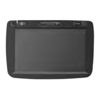
| Resolution | 480 x 272 pixels |
| Auxiliary Input | Yes |
| Voice Control | No |
| Compatibility | Renault vehicles |
| Navigation | Yes |
Diagram illustrating audio, video, camera inputs, monitor output, and control interfaces.
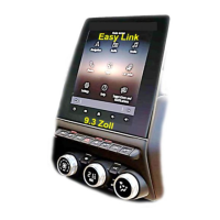
Details the buttons and functions of the center control unit for navigation and settings.
Step-by-step visual guide for disassembling and handling interface components during installation.
Instructions on correctly connecting flexible flat cables, emphasizing proper locking techniques.
Details pin assignments for the 24-pin connector, including CAN bus and power connections.
Outlines connections for 12V BATT, 12V ACC, Ground, and reverse signal trigger inputs.
Guides on resolving issues where the monitor fails to display images, checking flat cables.
Covers troubleshooting for no camera or video image, including DIP switch settings.
Explains reverse image blackouts and proper camera power sourcing based on CAN box control.