EasyManuals Logo

Renesas RA6M Series User Manual

Renesas RA6M Series
30 pages
To Next Page IconTo Next Page
To Previous Page IconTo Previous Page
Page #21 background imageLoading...
Page #21 background image
Renesas RA Family AIK-RA6M3, v1 User's Manual
R12UZ0143EE0100 Rev.0.1 Page
18
of 25
Oct.15.23
5.2.12 LEDs
There are 5 LEDs provided on the AIK-RA6M3. In addition, the Ethernet connector has built-in link status
and link speed LEDs.
The behavior of the LEDs on the AIK-RA6M3 is described in the following table.
Table 11. AIK-RA6M3 LED Functions
Designator
Color
Function
MCU Control Port
LED1
Blue
User LED
P908
LED1
Green
User LED
P907
LED1
Red
User LED
P906
LED2
Blue
Power on indicator
+3.3V
LED3
White
Power on indicator
+5V
LED4
Yellow
J-Link OB Status
J-Link OB MCU
The User LEDs may be isolated from the Main MCU, so the associated ports can be used for other
purposes.
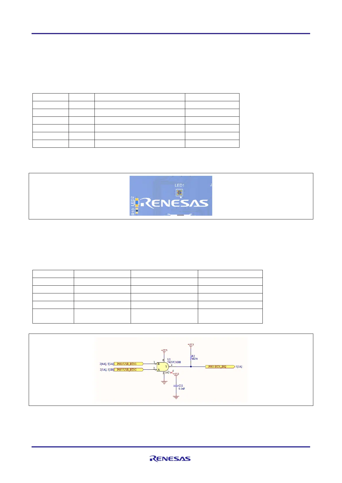
Figure 15. Power and User LEDs
5.2.13 Switches
Three miniature, momentary, mechanical push-button type SMT switches are mounted on AIK-RA6M3.
Pressing the Reset switch (S1) generates a reset signal to restart the Main MCU.
Table 12. AIK-RA6M3 Switches
Designator
Function
MCU Control Port
Button Color
S1
MCU Reset Switch
RESET#
Red
S2
User Switch
P007
Blue
S3
User Switch
P003
Blue
S2 + S3
And Gate
P005
S4
UART/SPI – IIC
DIP Switch
White x2
Figure 16. S2 + S3 User Switches
The User Switches S2 and S3 if pressed together can be used for interrupt operation

Questions and Answers:

Question and Answer IconNeed help?

Do you have a question about the Renesas RA6M Series and is the answer not in the manual?

Renesas RA6M Series Specifications

General IconGeneral
BrandRenesas
ModelRA6M Series
CategoryMicrocontrollers
LanguageEnglish

Related product manuals