1-6
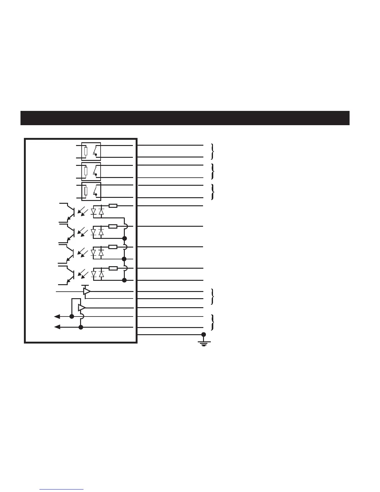
Wiring diagram (with output groupings shown)
CAUTION: The power supply 0 V should be terminated at the machine ground (“star point”). A negative supply can be used, when
wired appropriately.
NOTE: Inputs P2-P4 are the difference between the RMI and RMI-Q wiring, as these inputs allow multiple radio probes or tool setters
to be used.
RMI-Q
5 V
Driver
Driver
12 V to 30 V
0 V
Screen
Probe status 1 (SSR)
Low battery (SSR)
Error (SSR)
Machine start input [P1]
Machine start input [P2] (see notes)
Machine start input [P3] (see notes)
Machine start input [P4] (see notes)
Machine start return
Probe status 2a
(5 V isolated driven skip)
Probe status 2b
Power supply (12 V to 30 V)
Machine ground (“star point”)
Signal
Return
Turquoise
Turquoise/black
Violet
Violet/black
Green
Green/black
White
Pink
White/red
White/blue
Brown
Yellow
Grey
Orange
Red
Black
Green/yellow

 Loading...