16
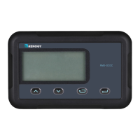
LCD Menu Overview
8. House Battery SOC Icon
Indicates the estimated state of charge of the house battery. State
of charge is voltage based and will be split into 4 bars each
representing 25% increments for a total of 100%. Factors such as
temperature, charge, and discharge can affect the state of charge.
To get the most accurate SOC readings, the battery needs to rest
in the open circuit state for at least 30-45min.
9. Alternator Charging Arrow
Shows that alternator is charging the starter battery or house battery
circuits.
10. Alternator Icon
Displays when connected to a starter battery successfully. Charging
will be indicative by the charging arrow mentioned above.
11. Battery Parameters
Battery Amps (A), Historical Kilowatt-hour Generation (KWH),
Voltage (V), and Temperature (◦C or ◦F) relevant to the starter battery.
12. Starter Battery Icon
When “S” is shown with parameters, it refers to the starter battery
parameters.
Navigate through the RMS-DCDC screens by pressing the page
up or page down keys.