Do you have a question about the Renogy Wanderer 30A PWM and is the answer not in the manual?
General safety guidelines before installation and operation of the charge controller.
Specific safety precautions for the charge controller and its connections.
Precautions for handling and connecting batteries to the charge controller.
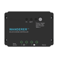
Highlights of the Wanderer charge controller's capabilities and functionalities.
Explanation of Pulse Width Modulation charging, including its 4 stages.
Measures battery temperature for accurate charge compensation.
Enables wireless monitoring and parameter adjustment via the Renogy BT App.
Procedure for connecting battery and solar panels to the controller.
Guidelines for selecting a suitable location and mounting the controller.
Instructions for selecting the correct battery type for the charge controller.
Details on PV and BATT LED indicators for monitoring controller status.
Recommended periodic tasks for optimal controller performance.
Information on wire sizing and recommended fuse ratings for protection.
Key electrical parameters and ratings of the charge controller.
Charging voltage and current settings for different battery types.
| Model | Wanderer 30A PWM |
|---|---|
| Type | PWM Solar Charge Controller |
| Rated Charging Current | 30A |
| System Voltage | 12V/24V Auto |
| Max. PV Input Voltage | 50V |
| Max. PV Input Power (12V system) | 400W |
| Max. PV Input Power (24V system) | 800W |
| Battery Types Supported | Sealed, Gel, Flooded, Lithium |
| Operating Temperature | -35°C to +55°C |
| Storage Temperature | -35°C to +80°C |
| Self-consumption | ≤ 10mA |
| Temperature Compensation | -3mV/°C/2V |
| Protection Features | Overload, Short Circuit, Reverse Polarity |
| Equalization Voltage | 14.6V (12V system) / 29.2V (24V system) |
| Boost Voltage | 14.4V (12V system) / 28.8V (24V system) |
| Float Voltage | 13.7V |