11 12
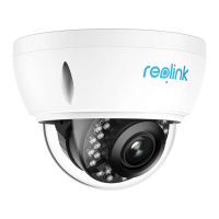
Loosenthetwoscrewsonboth
sidesofthecameraandadjust
thecameraviewingangle.
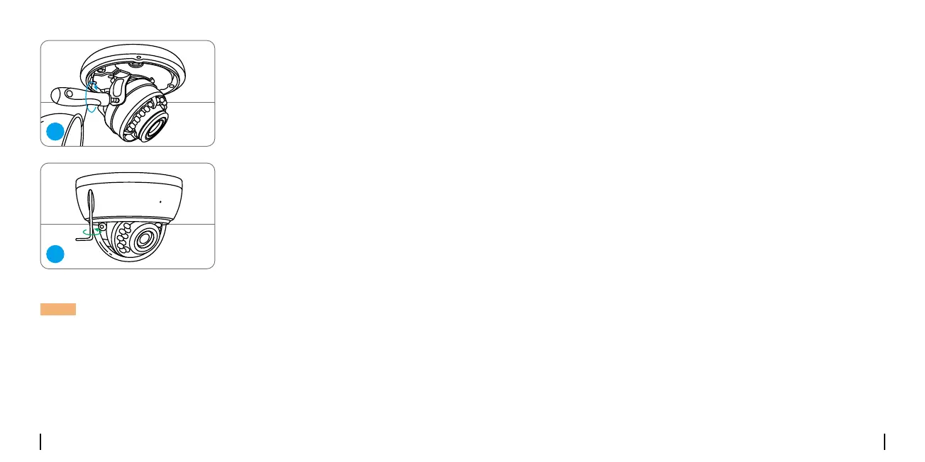
Tighten the screws and screw the
coverbacktothecamera.
4
5
Troubleshooting
•Makesureyourcameraispoweredonproperly.ThePoEcamerashould
bepoweredbyaPoEswitch/injector,aReolinkNVRora12Vpower
adapter.
•IfthecameraisconnectedtoaPoEdeviceaslistedabove,connectitto
anotherPoEportandcheckagain.
•TryagainwithanotherEthernetcable.
Ifyourcameraisnotpoweringon,pleasetrythefollowingsolutions:
Camera is not Powering on
For PoE Camera
For WiFi Camera
•Plugthecameraintoadierentoutletandseeifitworks.
•Poweronthecamerawithanotherworking12V1ADCadapterandsee
ifitworks.
Ifthesewon’twork,contactReolinkSupport.
NOTE:TheinstallationmethodstakethePoEcameraasanexampleand
alsoapplytotheWiFicamera.
 Loading...