English English3 4
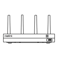
NVR Introduction
54 6 7 8 10 11
1 2 3
9
HDD LED
2
USB Port
3
Power LED
1
Reset
4
Power Input
5
USB Port
6
HDMI Port
7
LAN Port (For IPC)
11
VGA Port
8
Audio Out
9
LAN Port(For Internet)
10
Dierent states of the status LEDs:
Power LED: Solid green to indicate the NVR is powered on.
HDD LED: Flashing red to indicate the hard drive is operating properly.
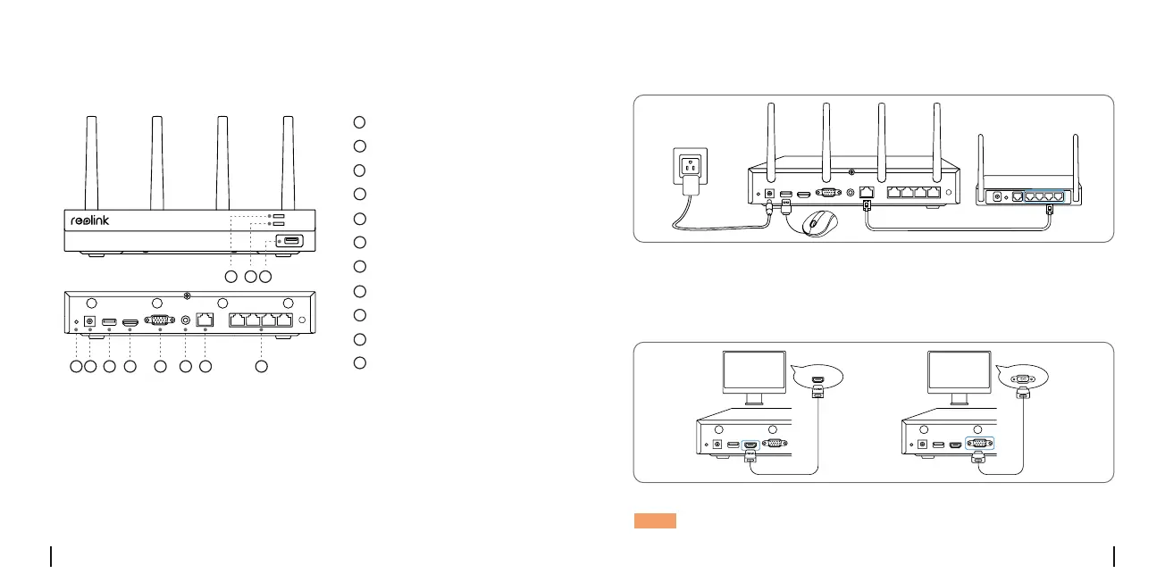
Connection Diagram
1.Connect the included power adapter to the NVR and a power outlet.
2.Connect the NVR to your router with an Ethernet cable (if you hope
to use it remotely).
Next, connect the mouse to the USB port of the NVR.
3.Connect the NVR to the monitor with a VGA or HDMI cable.
NOTE: There is no VGA cable and monitor included in the package.
HDMI
VG
A
NVR
Router
 Loading...