1.1 Mounting
The unit must only be located in dry interior locations. It
is not suitable for installation in hazardous locations and
should not be placed close to any electromagnetic fields. The
controller must additionally be supplied from a double-pole
switch with contact gap of at least 3 mm. Please pay attention
to separate routing of sensor cables and mains cables.
1. Unscrew the cross-head screw from the cover and
remove it along with the cover from the housing.
2. Mark the upper fastening point on the wall and drill and
fasten the enclosed wall plug and screw leaving the head
protruding.
3. Hang the housing from the upper fastening point and
mark the lower fastening point through the hole in the
terminal box (centres 130 mm). Drill and insert the lower
wall plug.
4. Fasten the housing to the wall with lower fastening screw
and tighten.
1. Installation
WARNING!
Alwaysswitch-offpowersupplyand
disconnect the controller from the
mains before opening the housing!
1.2 Electrical connection
The power supply to the controller must be carried out via
an external power switch (last step!) and the supply voltage
must be 220 ... 240 V~ (50 ... 60 Hz). Flexible cables must be
attached to the housing with the enclosed strain relief and
the corresponding screws.
Depending on the version, the controller is equipped with
either 1 relay (PG 66.30 and PG 67.30) or 2 relays (PG 68.30
and PG 69.30) to which loads such as pumps, valves, etc.
can be connected:
• Relay 1
18 = conductor R1
17 = neutral conductor N
13 = ground clamp
• Relay 2 (PG 68.30 and 69.30)
16 = conductor R2
15 = neutral conductor N
14 = ground clamp
Temperature sensors (S1 to S4) have to be connected
to the following terminals (either polarity):
1 / 2 = sensor 1 (e.g. sensor collector 1)
3 / 4 = sensor 2 (e.g. sensor store 1)
5 / 6 = sensor 3 (e.g. store top sensor)
7 / 8 = sensor 4 (e.g. return temperature sensor)
The power supply connection has to be carried out via
the following terminals:
19 = neutral conductor N
20 = conductor L
12 = ground clamp
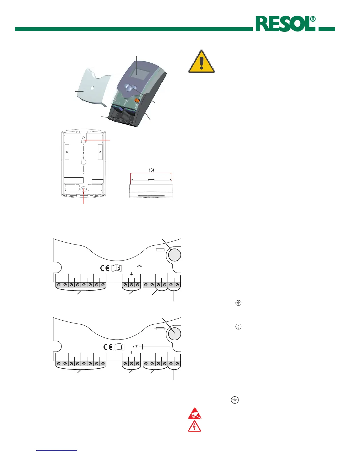
mains terminals
fuse
load terminals
sensor terminals
fastening
fastening
ground terminals
Electrostatic discharge can lead to damage to elec-
tronic components!
Dangerous voltage!

 Loading...