The Detector and Magnet should be mounted
using the double sided adhesive pads or screws
provided.
Note: If mounting the device using the adhesive
pads, ensure that the mounting surfaces are
clean and dry before mounting.
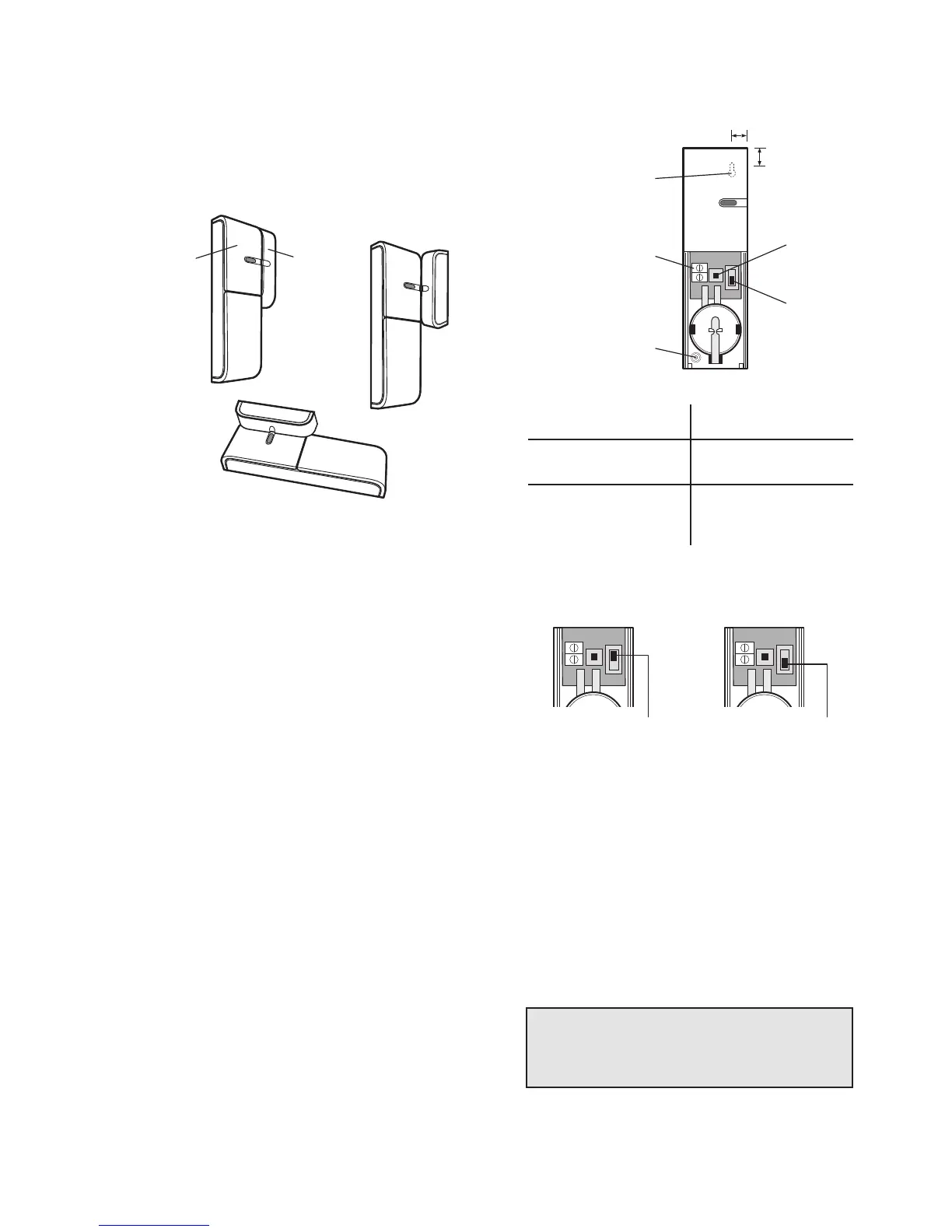
4.
If fixing the detector with screws first remove
the battery holder by carefully tilting up the
end and pulling away from the printed circuit
board (PCB).
The top of the Detector is secured by hanging
the keyhole slot over the head of the 10mm pan
head screw. The bottom of the Detector is
secured using the 12mm counter-sunk head
screw fitted within the battery compartment.
Carefully drill out the centre of the fixing screw
hole in the battery compartment using a 3mm
drill. Fit the Magnet using the two 15mm fixing
screws. Do not over- tighten the screws as this
may distort or damage the casing.
5. If an additional wired
Door/Window
is required,
this should be wired to the terminal block
provided in the battery compartment.
The wired contact should be connected using
a maximum length of 1.5 metres of any of
the following:
–
6 core alarm cable
–
2 core bell wire (6 x 0.2mm minimum)
–
2 core 24AWG wire
A cable entry cut-out is provided beside the
terminal block in the battery cover.
6. Switch SW3 is used to enable/disable the
internal/external wired magnetic contact.
Position of SW3 Function
INT. Internal Contact ON
INT./EXT. Internal and External
Contacts ON
7. Set the
Door/Window
Detector by setting the
position of the switch (SW3).
If setting to the INT. position, only the internal
contact will be active. When two contacts are in
use for internal and external connection
simultaneously (INT./EXT. position), only one
activation will be counted if one of the contacts
is opened. If one contact is left open and the
other closed contact is opened then an
activation will be counted.
If using external contacts wired to the Detector,
set to the INT./EXT. position.
8. Refit the battery cover.
17