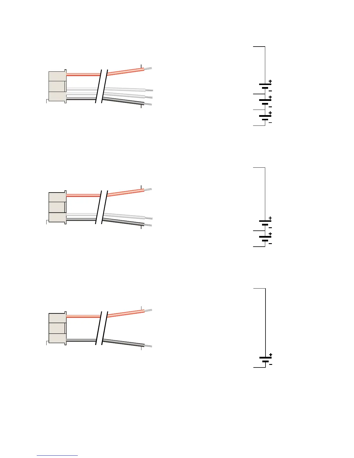
Pin 1
Red
Black
Pack positive
Node 2
Node 1
Pack negative
3s Pack
Pack positive
(red), 11.1V*
Node 2, 7.4V*
Node 1, 3.7V*
Pack negative
(blk), 0V
Cell 3
Cell 2
Cell 1
* Nominal voltage with
respect to pack negative
FMA Cellpro Connector/FMA Wiring Mode
Pin 1
Red
Black
Pack positive
Node 1
Pack negative
2s Pack
Pack positive
(red), 7.4V*
Node 1, 3.7V*
Pack negative
(blk), 0V
Cell 2
Cell 1
* Nominal voltage with
respect to pack negative
FMA Cellpro Connector/FMA Wiring Mode
Pin 1
Red
Black
Pack positive
Pack negative
1s Pack
Pack positive
(red), 3.7V*
Pack negative
(blk), 0V
Cell 1
* Nominal voltage with
respect to pack negative
NOTE: In the above FMA wiring scheme, when the battery has fewer than 5 cells, the red wire always
connects to Pack positive, and the unused balance (node) wires are left un-connected from the battery.
Always remove unused wires from the Cellpro battery pigtail by gently lifting each pin’s locking tab with a
hobby knife, and pulling the wire free of the housing.