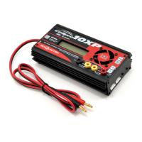
Pin 1
Black
Pack positive
Node 2
Node 1
Pack negative
3s Pack
Pack positive, 11.1V*
Node 2, 7.4V*
Node 1, 3.7V*
Pack negative
(blk), 0V
Cell 3
Cell 2
Cell 1
* Nominal voltage with
respect to pack negative
FMA Cellpro Connector/XH and EH Wiring Mode
Pin 1
Black
Pack positive
Node 1
Pack negative
2s Pack
Pack positive, 7.4V*
Node 1, 3.7V*
Pack negative
(blk), 0V
Cell 2
Cell 1
* Nominal voltage with
respect to pack negative
FMA Cellpro Connector/XH and EH Wiring Mode
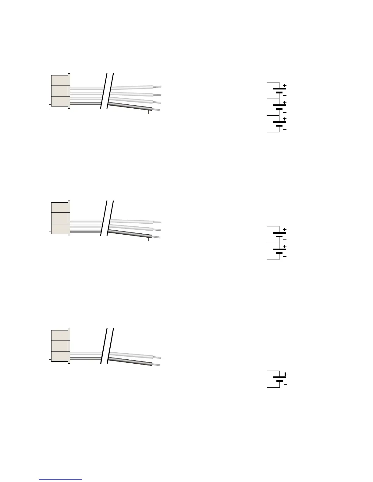
Pin 1
Black
Pack positive
Pack negative
1s Pack
Pack positive, 3.7V*
Pack negative
(blk), 0V
Cell 1
* Nominal voltage with
respect to pack negative
NOTE: In the above XH/EH wiring scheme, there are no un-used wires between any of the nodes and/or
pack positive like the FMA wiring scheme. Pack positive continually moves up by one with each additional
cell added to the pack. Always remove unused wires from the Cellpro battery pigtail by gently lifting the
pin’s locking tab with a hobby knife, and pulling the wire free of the housing.