EasyManua.ls Logo

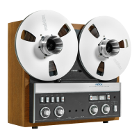
Revox A77

Revox A77
92 pages
To Next Page IconTo Next Page
To Previous Page IconTo Previous Page
Loading...
ALIGNMENT
INSTRUCTIONS
REVOX
A
77
DOLBY
Hem
Operation
Alignment
Procedure
Test
Equipment
Tape
Speed
ips
Frequency
Voltage
Testpoint
Where
to
adjust
1.
Adjustment
of
regulated
Voltage
Adjust
exactly
to
nominal
21
volts
Multimeter
7.5
+
21
V
DC
Yellow
wire
ED
1
P
106
2.
Adjustment
of
Tacho
Head
(S.M.
6.2.1.)
Alter
head
position
to
obtain
specified
tacho
voltage
Electronic
Volt-
meter
3.75
40
m V
AC
El -
E2
mounting
screws
of
tacho
-
head
3.
Bias-
Filter
record
(S.M.
6.4.3.)
Adjust
for
minimum
voltage
Electronic Volt-
meter
7.5
120
kHz
<
300
mV
see
fig.
6.4.-63/64
L
501
4.
Bias-
Filter,
replay
(S.M.
6.4.4.)
Adjust
for
minimum
voltage
Electronic Volt-
meter
7.5
120
kHz
<
50
mV
Wiper
P
801
L
801
5.
Motor
Speed
(S.M.
6.2.2.)
Adjust
tacho
frequency
(
mea-
sure
over
at
least
10
sec.)
Digital
Counter
7.5
3.75
1601
Hz
800
Hz
10
V
Pin
2
on
T
201
T
201
P
201
6.
Oscillator
and
Bias
adjust
As
per
Service
Manual
6.4.
Adjust
dummy
load
Electr.Voltmeter
Digital
Counter
Digital
Counter
7.5
7.5
7.5
120
kHz
120
kHz ±
5
kHz
120
kHz ±
5
kHz
2
Track
21
VAC
HB3-HB6
HB3-HB6
HB3-HB6
blue &
orange
wire
Dummy
load
L
601
7.
DOLBY
record
adjustments
DOLBY "
OUT"
DOLBY "
IN"
Turn
FET-bias
off, set
gain
control
to
minimum
amplification
DOLBY
switch
0
in
position
"OUT"
Connect
Audio
Generator
to
"AUX"
inputs,
Adjust
level
on
Generator
Adjust
level
on
Generator
DOLBY
switch
in
pos.
" IN",
measure
voltage
rise
on
DOLBY
output
Level
adjustment
Level
reduction
by
2
dB
T19
T
19
VTVM
T
19
VTVM
T
19
VTVM
T
19
VTVM
T
19
VTVM
5
kHz
5
kHz
5
kHz
5
kHz
5
kHz
5
kHz
'N.
,
0.45
mV
3
mV
2.6
mV
'‘,
7
mV
(+8
dB)
8.2
mV
(+10dB)
-2
dB
P1,
P2
P3,
P4
P3,
P4
P3,
P4
P3.
P4
P
101
r (
CH
I,
CH
II)
P
102
r (
CH
I,
CH
II)
Generator
Generator
Generator
P
102
r
P
101
r
8.
DOLBY
replay
adjustments
DOLBY "
OUT"
DOLBY "
IN"
Turn
FET
bias
off,
Set
gain
control
to
min.
amplification.
DOLBY
switch
0
in
pos.
"
OUT"
Connect
Audio
Generator
to
DOLBY
inputs (
with
test
clips).
Adjust
level
on
generator
DOLBY
switch
0
in
pos.
"
IN"
Adjust
level
reduction
on
DOLBY
outputs
Level
increase
by
2
dB
T
19
T
19
VTVM
T
19
VTVM
T
19
VTVM
5
kHz
5
kHz
5
kHz
5
kHz
7.6
mV
-10
dB
=
2.4
mV
+2
dB
= 3
mV
P5,
P6
P7,
P8
P7,
P8
P7,
P8
P
101
p (
CH
I,
CH
II)
P
102
p (
CH
I,
CH
II)
P
102
p
P
101
r
9.
VU-
Meter
calibration
Connect
Audio
Generator
to
"
AUX"
inputs,
Adjust
generator
output
level
Calibrate
VU-
meters
T
19
or
generator
1
kHz
1
kHz
1
kHz
'\,
13
mV
100
mV
0
VU
P1,
P2
P
103
p
10.
11.
Balance
Adjustment
Playback
head
azimuth
adjustment
As
per
Service
Manual
sections
6.3.1.
and
6.3.2.
DOLBY
reference
tape
12.
Playback
level
off
test
tape
Playback
level
calibration
VU-
Meter
7.5
185
nWb/m
= 0
VU
P
801
print
077.720
13.
Frequency
response
check
As
per
Service
Manual
6.3.4.
and
additional
instructions.
14.
Record
head
azimuth
adjustment
"REC.
CAL"
pot-
meters
CD/Ce4
fully
ccw.
T19
generator
level ('\
,
13
mV)
adjusted
for
0
VU
indication.
Reduce
generator
level -
20
dB
Adjust
azimuth
as
per
S.M.
6.5.3.
10
kHz
10
kHz
VU =
0
dB
-20
dB
15.
RF
Bias
Adjustment
As
per
Service
Manual
6.5.2.
A U
for
Scotch
207
T19
_
7.5
3.75
4
dB
5
dB
OUTPUT
CH
I,
CH
II

Other manuals for Revox A77

Related product manuals