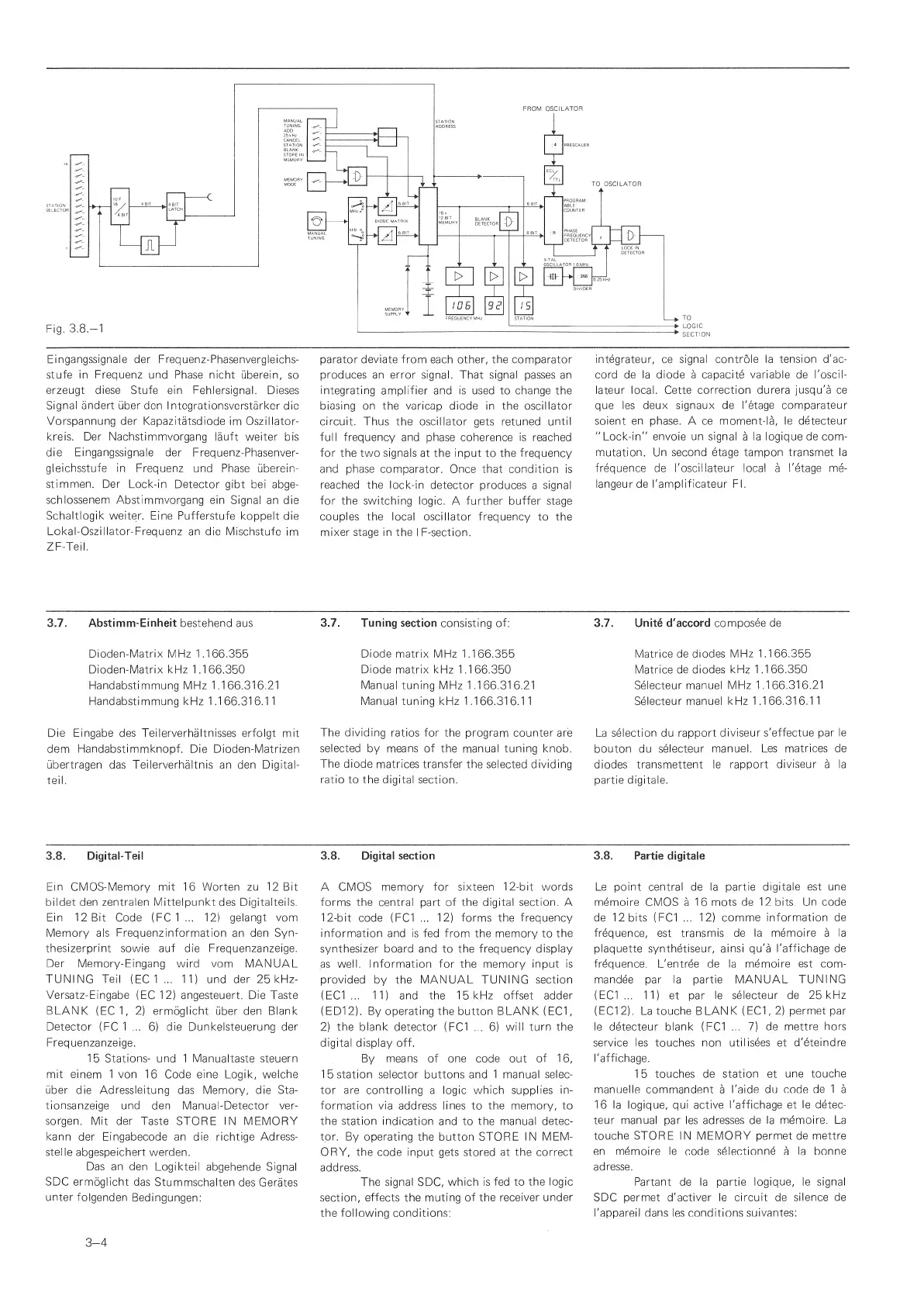
Eingangssignale der Frequenz-Phasenvergleichs-
stufe in Frequenz und
Phase
nicht
uberein, so
erzeugt diese Stufe ein
Fehlersignal. Dieses
Signal andert
uber den
I
ntegrationsverstarker
die
Vorspannung der Kapazitatsdiode
im Oszillator-
kreis. Der Nachstinnmvorgang
lauft waiter bis
die
Eingangssignale
der Frequenz-Phasenver-
gleichsstufe in
Frequenz und
Phase uberein-
stinnmen. Der Lock-in
Detector
gibt bei abge-
schlossenem Abstimmvorgang
ein Signal
an die
Schaltlogik waiter.
Fine Pufferstufe
koppeltdie
Lokal-Oszillator-Frequenz
an die Mischstufe
im
ZF-Teil.
parator deviate from
each other,
the
comparator
produces an error
signal. That
signal
passes an
integrating
amplifier and is used to change the
biasing on
the
varicap diode
in the oscillator
circuit. Thus
the
oscillator gets
retuned
until
full frequency and
phase
coherence is
reached
for the two signals
at
the input
to the frequency
and phase
comiparator. Once that condition
is
reached
the lock-in
detector produces
a
signal
for
the switching logic.
A
further
buffer
stage
couples
the local oscillator frequency
to the
mixer stage in
the
I
F-section.
integrateur, ce
signal controle la tension d'ac-
cord de la diode a capacite
variable
de
I'oscil-
lateur local. Cette
correction durera jusqu'a ce
que les
deux signaux de I'etage comparateur
soient
en
phase. A ce moment-la,
le detecteur
"Lock-in" envoie un signal
a
la logique de com-
mutation. Un second etage tampon transmet
la
frequence
de I'oscillateur local
a
I'etage
me-
langeurde I'amplificateur FI.
3.7.
Abstimm-Einheit bestehend aus
Dioden-Matrix MFIz 1 .1
66.355
Dioden-Matrix kHz 1 .1
66.350
Handabstimmung MHz
1 .1
66.31
6.21
Handabstimmung kHz 1
.1 66.31
6.1
1
Die
Eingabe
des
Teilerverhaltnisses erfoigt mit
dem
Handabstimmknopf.
Die Dioden-Matrizen
ubertragen das Teilerverhaltnis an den Digital-
teil.
3.7.
Tuning
section
consisting
of:
Diode
matrix
MHz
1.166.355
Diode
matrix
kHz
1
.1
66.350
Manual
tuning MHz 1 .1 66.31 6.21
Manual tuning kHz 1
.1 66.31
6.1
1
The dividing
ratios for the program counter
are
selected
by means of the
manual tuning knob.
The diode
matrices
transfer the selected dividing
ratio to
the digital section.
3.7.
Unite d'accord composee de
Matrice
de diodes MHz
1.1 66.355
Matrice
de diodes kHz 1
.1 66.350
Selecteur manuel
MHz
1.166.316.21
Selecteur manuel
kHz 1.1 66.31
6.1
1
La
selection
du rapport
diviseur
s'effectue par le
bouton du
selecteur manuel.
Les matrices de
diodes transmettent le
rapport
diviseur
a la
partie digitale.
3.8.
Digital-Teil
Ein
CMOS-Memory mit 1
6
Worten zu
1
2 Bit
bildet
den zentralen Mittelpunkt
des Digitalteils.
Ein 1
2 Bit Code (FC
1 ... 1
2)
gelangt vom
Memory
als Frequenzinformation
an den
Syn-
thesizerprint
sowie auf die Frequenzanzeige.
Der Memory-Eingang
wird vom MANUAL
TUNING
Teil
(EC
1 ...
11)
und
der 25kHz-
Versatz- Eingabe
(EC
1
2)
angesteuert. Die Taste
BLANK
(EC1,
2)
ermoglicht
uber den
Blank
Detector
(FC
1 ...
6)
die
Dunkelsteuerung
der
Frequenzanzeige.
1
5
Stations- und 1
Manualtaste
steuern
mit einem
1
von
16 Code
eine
Logik,
welche
uber
die
Adressleitung
das Memory, die
Sta-
tionsanzeige und
den Manual-Detector
ver-
sorgen.
Mit der Taste STORE I
N
MEMORY
kann
der
Eingabecode
an die richtige
Adress-
stelle
abgespeichert werden.
Das an den
Logikteil
abgehende Signal
SDC ermoglicht
das
Stummschalten
des Cerates
unter
folgenden
Bedingungen:
3.8.
Digital section
A CMOS
memory for sixteen
1 2-bit words
forms the
central part of the
digital section.
A
1
2-bit code
(FC1
...
1
2)
forms
the
frequency
information
and is fed from the memory to
the
synthesizer board and
to
the frequency display
as
well. Information for
the memory
input is
provided
by the MANUAL TUNING section
(EC1
...
1
1 )
and the
1
5
kHz offset adder
(EDI
2).
By operating the button BLAN
K
(EC1
,
2)
the blank detector
(FC1
...
6)
will turn the
digital display off.
By means of one code
out
of
16,
1
5
station selector buttons and 1
manual selec-
tor are controlling
a
logic which supplies
in-
formation via
address
lines
to
the memory, to
the
station indication
and to
the manual detec-
tor.
By operating the button
STORE
IN MEM-
ORY,
the
code input gets
stored
at the correct
address.
The signal SDC,
which is
fed to
the
logic
section,
effects
the
muting of the
receiver
under
the following
conditions;
3.8. Partie
digitale
Le point central de la partie
digitale est
une
memoire CMOS
a
16 mots
de 12 bits. Un code
de
1
2
bits (
FC1
...
1
2}
comme
information de
frequence, est transmis de la
memoire
a
la
plaquette synthetiseur, ainsi qu'a
I'affichage de
frequence.
L'entree de la
memoire est com-
mandee par la partie
MANUAL
TUNI
NG
(EC1
...
1
1 )
et par
le selecteur de
25 kHz
(EC1
2).
La touche BLANK
(EC1
,
2)
permet
par
le detecteur blank
(FC1
...
7)
de
mettre hors
service
les touches non
utilisees
et
d'eteindre
I'affichage.
1
5
touches de
station
et
une
touche
manuelle commandent
a
I'aide du code
de 1
a
16 la logique, qui active
I'affichage et
le detec-
teur manual
par les
adresses de la memoire. La
touche STORE IN MEMORY permet
de mettre
en memoire
le code
selectionne
a
la bonne
adresse.
Partant de la partie
logique, le signal
SDC permet d'activer le
circuit
de
silence de
I'appareil dans les
conditions suivantes;
3-4
 Loading...