I
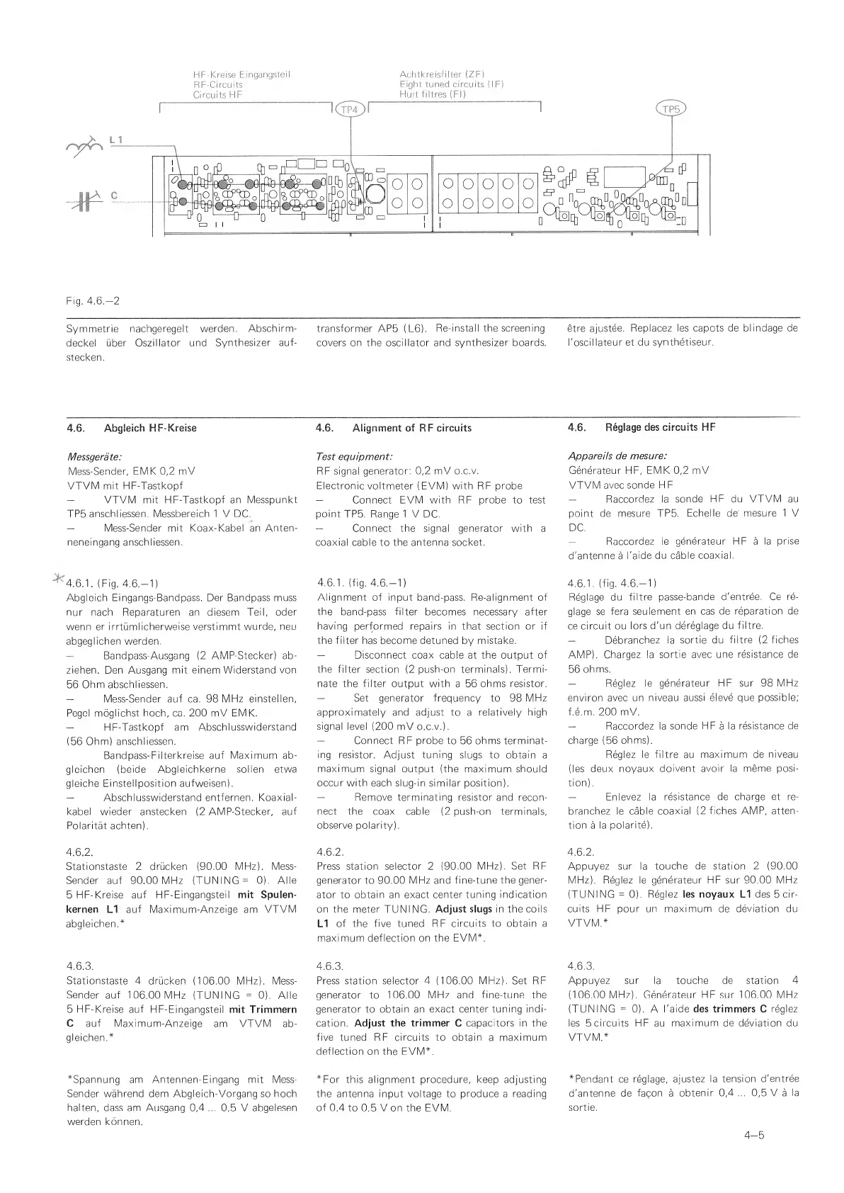
Fig.
4.6.-2
Symmetrie
nachgeregelt
werden.
Abschirm-
transformer AP5
(L6).
Re-install the screening
etre
ajustee.
Replacez
les
capots
de blindage de
deckel
uber Oszillator
und
Synthesizer
auf-
covers on
the
oscillator and synthesizer
boards. I'oscillateur
et du
synthetiseur.
stecken.
4.6.
Abgfeich
HF*Kreise
Messgerate:
Mess-Sender,
EMK
0,2
mV
VTVM mit HF-Tastkopf
VTVM mit FIF-Tastkopf
an Messpunkt
TP5
anschliessen. Messbereich
1
V DC.
—
Mess-Sender mit
Koax-Kabel an Anten-
neneingang anschliessen.
'4.6.1.
(Fig. 4.6.-1)
Abgleich Eingangs-Bandpass. Der Bandpass muss
nur
nach Reparaturen an diesem Teil,
oder
wenn
er
irrtumlicherweise
verstimmt wurde,
neu
abgeglichen werden.
—
Bandpass-Ausgang
(2
AMP-Stecker) ab-
ziehen. Den
Ausgang
mit einem
Widerstand von
56
Ohm abschliessen.
—
Mess-Sender
auf
ca. 98
MFIz einstellen,
Pegel moglichst
hoch,
ca.
200 mV EMK.
—
HF-Tastkopf am
Abschlusswiderstand
(56
Ohm)
anschliessen.
Bandpass-Filterkreise auf
Maximum ab-
glcichen
(beide Abgleichkerne
sollen etwa
gleiche Einstellposition
aufweisen).
—
Abschlusswiderstand
entfernen. Koaxial-
kabel wieder anstecken
(2
AMP-Stecker,
auf
Polaritat achten).
4.6.2.
Stationstaste 2 drucken
(90.00
MHz). Mess-
Sender auf 90.00 MHz (TUNING
=
0).
Alle
5
HF-Kreise auf HF-Eingangsteil
mit Spulen-
kernen
LI auf Maximum-Anzeige
am
VTVM
abgleichen.*
4.6.3.
Stationstaste
4 drucken
(106.00
MHz).
Mess-
Sender
auf 106.00
MHz (TUNING
=
0).
Alle
5
HF-Kreise
auf HF-Eingangsteil
mit
Trimmern
C auf
Maximum-Anzeige
am VTVM ab-
gleichen.*
*Spannung am
Antennen-Eingang
mit
Mess-
Sender wahrend
dem Abgleich-Vorgang so hoch
halten, dass am Ausgang
0,4
...
0,5
V
abgelesen
werden
konnen.
4.6.
Alignment of
RF
circuits
Test
equipment:
RF signal
generator:
0,2
mV
o.c.v.
Electronic voltmeter
(EVM)
with RF probe
—
Connect
EVM
with
RF
probe to test
point
TP5. Range
1
V DC.
Connect
the
signal
generator with a
coaxial
cable to the
antenna socket.
4.6.1. (fig. 4.6.-1)
Alignment of
input band-pass. Re-alignment of
the
band-pass
filter
becomes necessary after
having
performed repairs
in
that section or
if
the filter has become detuned
by
mistake.
—
Disconnect coax cable at the output
of
the filter
section
(2
push-on terminals). Termi-
nate the filter output with
a 56
ohms resistor.
“
Set
generator frequency to 98
MHz
approximately and
adjust to a
relatively high
signal level
(200
mV o.c.v.).
—
Connect RF probe to
56
ohms terminat-
ing
resistor. Adjust
tuning
slugs to obtain
a
maximum
signal output (the
maximum should
occur with
each slug-in similar
position).
—
Remove terminating
resistor and recon-
nect
the coax cable
(2
push-on terminals,
observe
polarity).
4.6.2.
Press station
selector
2
(90.00
MHz).
Set RF
generator to 90.00
MHz
and
fine-tune the
gener-
ator to
obtain an exact center
tuning indication
on the meter TUNING.
Adjust slugs in the
coils
LI
of the five
tuned
RF
circuits to obtain a
maximum deflection on
the EVM*.
4.6.3.
Press station selector
4
(106.00
MHz). Set
RF
generator
to
106.00
MHz
and
fine-tune
the
generator
to
obtain an exact
center
tuning indi-
cation.
Adjust the trimmer
C
capacitors
in the
five
tuned RF circuits to obtain
a
maximum
deflection
on the EVM*.
*For
this alignment procedure,
keep
adjusting
the antenna input voltage to produce
a
reading
of 0.4 to
0.5 Von
the
EVM.
4.6.
Reglage des
circuits HF
Appareils de
mesure:
Generateur
HF, EMK
0,2
mV
VTVM avec
sonde
H F
~
Raccordez
la sonde
HF
du VTVM au
point de
mesure
TP5.
Echelle de' mesure
1 V
DC.
^
Raccordez le
generateur HF a
la prise
d'antenne
a
I'aide
du cable
coaxial.
4.6.1.
(fig.
4.6.-1)
Reglage
du filtre
passe-bande
d'entree.
Ce
re-
glage se
fera
seulement
en
cas
de reparation
de
ce
circuit ou
lors d'un
dereglage du
filtre.
—
Debranchez la
sortie du
filtre
(2
fiches
,AMP).
Chargez la
sortie avec
une resistance de
56
ohms.
—
Reglez le
generateur
HF
sur
98
MHz
environ avec
un niveau aussi
eleve que possible;
f.e.m.
200
mV.
—
Raccordez la
sonde HF
a
la resistance de
charge
(56
ohms).
Reglez le filtre au
maximum de
niveau
(les deux noyaux
doivent
avoir la meme posi-
tion).
—
Enlevez la
resistance de charge
et
re-
branchez le
cable coaxial
(2
fiches AMP, atten-
tion
a
la
polarite).
4.6.2.
Appuyez sur la touche
de station
2
(90.00
MHz). Reglez le generateur HF sur
90.00 MHz
(TUNING
=
0).
Reglez les noyaux
L1
des
5
cir-
cuits HF
pour
un maximum
de
deviation du
VTVM.*
4.6.3.
Appuyez sur
la
touche de station
4
(106.00
MHz).
Generateur
HF
sur
106.00 MHz
(TUNING
=
0). A
I'aide des trimmers
C
reglez
les
5
circuits HF
au
maximum
de
deviation du
VTVM.*
*Pendant ce
reglage,
ajustez
la tension
d'entree
d'antenne de
facon
a
obtenir
0,4
...
0,5
V
a
la
sortie.
4-5
 Loading...