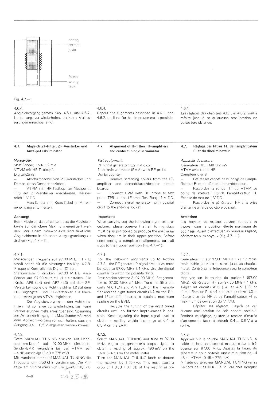
richtig
correct
juste
falsch
wrong
faux
Fig.
4.7.-1
4.6.4.
Abgleichvorgang gemass Kap. 4.6.1. und 4.6.2.
ist so lange
zu
wiederholen, bis
keine
Verbes-
serungen erreichbar
sind.
4.6.4.
Repeat
the
alignments described in 4.6.1. and
4.6.2.
until no further improvement is possible.
4.6.4.
Les
reglages des chapitres 4.6.1
.
et 4.6.2. sont
a
refaire
jusqu'a ce
qu'aucune
amelioration
ne
puisse
etre obtenue.
4.7. Abgleich ZF-Fi!ter, ZF-Verstarker
und
Anzeige-Diskriminator
Messgerate:
Mess-Sender,
EMK
0,2
mV
VTVM mit HF-Tastkopf,
Digital-Zahler
—
Abschirmdeckel von ZF-Verstarker und
Demodulator/Decoder abziehen.
—
VTVM mit HF-Tastkopf an Messpunkt
TP5 auf
ZF-Verstarker anschliessen.
Messbe-
reich
1
V
DC.
—
Mess-Sender mit Koax-Kabel an Anten-
neneingang anschliessen.
Achtung:
Beim Abgleich darauf achten, dass die Abgleich-
kerne
auf das obere
Maximum einjustiert
wer-
den.
Vor
einem
Neu-Abgleich sind
samtiiche
Abgleichkerne in die obere Ausgangsstellung
zu
drehen (Fig.
4.7.—
1
).
4.7.1.
Mess-Sender Frequenz auf
97.00 MHz
±
1 kHz
stabil halten fur die
Messungen bis
Kap.
4.7.8.
Frequenz-Kontrolle
mit Digital-Zahler.
Station,staste
v3 driicken
(97.00
MHz).
Mess-
Sender auf
97.00 MHz
±
1 kHz einstellen. Die
Kreise
AP6 (L4) und AP7
(L3)
auf
dem ZF-
Verstarker
sowie die Achtkreisfilter
L2
auf dem
H
F-Eingangsteil und ZF-Verstarker auf Maxi-
mum-Anzeige
am VTVM abgleichen.
Der
Abgleichvorgang an den Achtkreis-
filtern
ist
so
lange zu wiederholen,
bis keine
Verbesserungen
mehr erreichbar sind.
Spannung
am
Antennen-Eingang
mit
Mess-Sender
wahrend
dem
Abgleich-Vorgang
so
hoch
halten,
dass
am
Ausgang
0,4
...
0,5
V
abgelesen
werden
konnen,
4.7.2.
Taste
MANUAL
TUNING drucken. Mit Hand-
abstimm-Knopf auf 97.00 MHz
einstellen;
Sender-EMK verandern bis
das VTVM auf
—4
dB ausschlagt
(0
dB
=
775 mV).
Mit Handabstimmknopf
MANUAL TUNING die
Frequenz
um
±
50
kHz verstimmen.
Die An-
zeige
am
VTVM
muss sich um
1
,3
dB
±
0,1
dB
4.7.
Alignment of
I
F-fliters,
I
F-amplifiers
and center tuning discriminator
Test
equipment:
RF signal generator;
0,2
mV o.c.v.
Electronic voltmeter (EVM) with RF probe
Digital counter
—
Remove
screening covers
from
the
I F-
amplifier and
demodulator/decoder circuit
boards.
—
Connect EVM with RF probe to test
point
TP5
on the I F-amplifier.
Range 1
V
DC.
—
Connect signal generator with coaxial
cable to the antenna socket.
Important:
When carrying
out the following alignment pro-
cedures,
please observe that all tuning slugs
must be so positioned to produce the maximum
when they are in their
upper
position. Before
commencing
a
complete re-alignment, turn all
slugs to their upper
position (fig.
4.7.—
1
).
4.7.1.
For the following alignments up to
section
4.7.8.,
the RF
generator's signal frequency must
be
kept to 97.00 MHz
±
1 kHz.
Use
the digital
counter
to
watch for possible drifts.
Press station selector
3
(97.00
MHz).
Set
genera-
tor to 97.00 MHz
±
1 kHz. Tune
the filter cir-
cuits AP6
(
L4)
and AP7
(
L3)
on the
I
F-ampli-
fier and the
eight
tuned
circuits L2 on the RF-
and I
F-amplifier boards to obtain a maximum
reading on the EVM.
Recycle the
tuning of the eight tuned
circuits until no further improvement is pos-
sible. Keep adjusting
the
input
signal level
to
obtain
a
reading within the range of
0.4
to
0.5
Von the EVM.
4.7.2.
Select MANUAL TUNING and
tune to 97.00
MHz. Adjust the
generator's output signal to
obtain
a
reading
of approx. 490 mV
on
the
EVM
(—4
dB
on the meter scale).
Turn the MANUAL TUNING
knob to detune
the receiver
by
±
50 kHz. This must cause a
drop of 1.3 dB
±0.1
dB
of the reading
as
ob-
4.7.
Reglage
des flltres
FI,
de Tamplificateur
FI et
du discriminateur
Appareils
de mesure:
Generateur
HF, EMK
0,2
mV
VTVM avec
sonde HF
Compteur
digital
—
Retirez
les
capots de
blindage de I'ampli-
ficateur
FI et
du demodulateur/decodeur.
—
Raccordez
la
sonde HF du VTVM au
point de mesure TP5 de I'amplificateur
FI.
Echelle
de
mesure 1
V DC.
—
Raccordez le generateur
HF
a
la
prise
d'antenne
a
I'aide
du
cable coaxial.
Attention:
Les noyaux
de reglage
doivent toujours se
trouver dans la
position
elevee maximum du
bobinage.
Avant d'effectuer
un nouveau reglage,
devissez tous les noyaux
(fig.
4.7.—
1
).
4.7.1.
Generateur HF sur 97.00
MHz
±
1 kHz
a
main-
ten ir stable pour les mesures jusqu'au
chapitre
4.7.8.
Controlez
la frequence avec le compteur
digital.
Appuyez
sur la touche
de station
3
(97.00
MHz). Generateur HF sur
97.00 MHz
±
1 kHz.
Reglez les circuits AP6 (
L4)
et AP7 (
L3)
de
I'amplificateur FI ainsi que les huit filtres
L2
de
I'etage d'entree HF
et
de I'amplificateur
FI
au
maximum de deviation du
VTVM.
Repetez les reglages jusqu'a ce qu'
aucune amelioration
ne
soit encore possible.
Pendant ce reglage, ajustez la tension
d'entree
d'antenne de facon
a
obtenir
0,4
...
0,5
V
a
la
sortie.
4.7.2.
Appuyez
sur la touche
MANUAL
TUNING. A
I'aide du
bouton d'accord
manuel
calez la fre-
quence sur 97.00
MHz.
Ajustez la f.e.m.
du
generateur pour obtenir
une
diminution de
—4
dB au
VTVM
(0
dB
-
775
mV).
A
I'aide du selecteur
MANUAL TUNING
variez
I'accord de
±
50 kHz. Le
VTVM doit indiquer
 Loading...