®
CtP9^
O
®
©
°
Jfi_
Q]
'^o
od?°
CD°n^
o
o
-o
o
o o o
o
o
o
o
o
~^L1)
^rj;.;:
(L2)
oPi
~0mr^O^n“^ci’
Qfl]
^
^
°
8^"=|s
a
d”Q
Donoa
dQ^dQoQ^
O
0^'=5^„n
(L3)
fJzC
/•!“’
( rF/
]
^
•^Ft'
'
F
Fig.
4.7.-2
absenken.
Die
Frequenz um
ilOOkhiz
verstimmen.
Die
Anzeige am
VTVM
muss sich
um
'7;51dB
±
0,5
dB
absenken.
Allenfalls die
Abstimmung des
Achtkreisfilters
leicht
korrigieren.
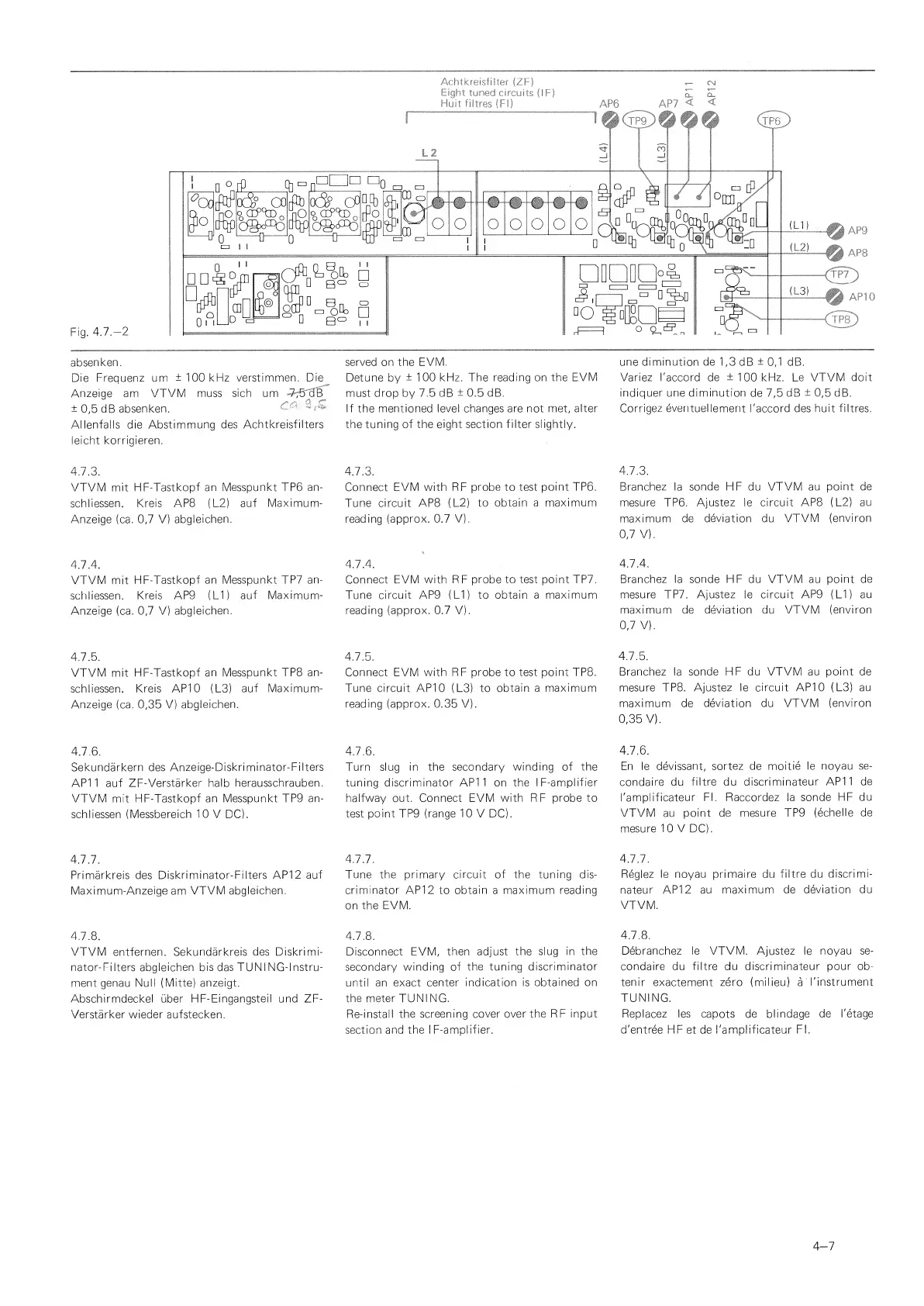
4.7.3.
VTVM mit
FIF-Tastkopf an Messpunkt TP6 an-
schliessen. Kreis
APB
(L2)
auf
Maximum-
Anzeige (ca.
0,7
V)
abgleichen.
4.7.4.
VTVM
mit
HF-Tastkopf
an Messpunkt TP7 an-
schliessen.
Kreis AP9
(LI) auf Maximum-
Anzeige
(ea. 0,7
V)
abgleichen.
4.7.5.
VTVM mit
HF-Tastkopf an
Messpunkt TP8 an-
schliessen.
Kreis AP10
(L3)
auf Maximum-
Anzeige
(ca.
0,35
V)
abgleichen.
4.7.6.
Sekundarkern des
Anzeige-Diskriminator-Filters
AP1
1
auf
ZF-Verstarker halb
herausschrauben.
VTVM mit HF-Tastkopf
an Messpunkt TP9
an-
schliessen (Messbereich
10
V
DC).
4.7.7.
Primarkreis des
Diskriminator-Filters
API
2
auf
Maximum-Anzeige
am
VTVM abgleichen.
4.7.8.
VTVM
entfernen.
Sekundarkreis des Diskrimi-
nator-Filters abgleichen bis
das
TUNI NG-lnstru-
ment genau Null (Mitte) anzeigt.
Abschirmdeckel uber
HF-Eingangsteil und
ZF-
Verstarker wieder aufstecken.
served on the EVM.
Detune by
±100
kHz. The
reading on the EVM
must drop by
7.5 dB
±
0.5 dB.
If the mentioned
level changes are not met, alter
the
tuning of the eight section filter slightly.
4.7.3.
Connect
EVM with RF
probe
to
test
point TP6.
Tune
circuit APB (
L2)
to obtain a
maximum
reading
(approx.
0.7 V).
4.7.4.
Connect EVM with RF
probe to test point TP7.
Tune
circuit
AP9
(LI) to obtain a
maximum
reading
(approx. 0.7
V).
4.7.5.
Connect EVM
with RF probe to test point TP8.
Tune circuit
AP10 (L3) to
obtain
a
maximum
reading (approx. 0.35 V).
4.7.6.
Turn
slug
in the secondary
winding of the
tuning discriminator AP1 1 on the
IF-amplifier
halfway out. Connect EVM
with
RF
probe to
test point TP9
(range 10
V
DC).
4.7.7.
Tune the primary circuit
of
the tuning dis-
criminator API
2 to
obtain
a maximum
reading
on the
EVM.
4.7.8.
Disconnect EVM,
then adjust
the slug in
the
secondary
winding of
the tuning
discriminator
until
an exact center
indication is
obtained on
the meter TUNING.
Re-install
the screening cover over
the
RF
input
section
and the IF-amplifier.
une
diminution de
1,3
dB
±
0,1
dB.
Variez I'accord de
±100
kHz. Le VTVM doit
indiquer une
diminution
de
7,5
dB
±
0,5
dB.
Corrigez
eventuellement
I'accord des
huit fibres.
4.7.3.
Branchez la
sonde HF
du
VTVM au point
de
mesure TP6.
Ajustez
le
circuit APB (
L2)
au
maximum de
deviation
du
VTVM
(environ
0,7
V).
4.7.4.
Branchez la sonde HF du VTVM au
point de
mesure TP7. Ajustez le circuit
AP9 (LI) au
maximum de
deviation
du VTVM
(environ
0,7
V).
4.7.5.
Branchez la sonde
HF
du VTVM au
point de
mesure TP8.
Ajustez
le
circuit AP10 (L3) au
maximum de deviation du VTVM
(environ
0,35
V).
4.7.6.
En le
devissant, sortez de
moitie le noyau
se-
condaire du
fibre du discriminateur
AP11 de
I'amplificateur
FI. Raccordez la
sonde HF
du
VTVM au
point de mesure TP9
(echelle de
mesure
1
0 V DC).
4.7.7.
Reglez le
noyau primaire du fibre du
discrimi-
nateur API
2
au
maximum de
deviation du
VTVM.
4.7.8.
Debranchez le
VTVM.
Ajustez le
noyau se-
condaire du
fibre du discriminateur pour ob-
tenir exactement
zero
(milieu)
a
' I'instrument
TUNING.
Replacez les capots de blindage
de I'etage
d'entree HF
et
de I'amplificateur
FI.
4-7
 Loading...