Do you have a question about the REXROTH IndraControl L65 and is the answer not in the manual?
Explains the structured format of safety instructions with signal words and symbols.
Defines signal words (danger, warning, caution, notice) and safety alert symbols.
Details operating, transport, and storage conditions like temperature, humidity, and air pressure.
Lists processor types, RAM specifications, and interface details for various controls.
Provides specifications for nominal voltage, tolerance, and power consumption of controls.
Provides guidelines for proper installation, including cable routing and clearances.
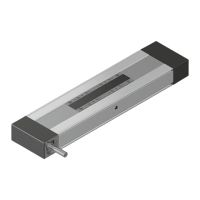
Shows detailed dimensional drawings of the L45, L65, L75, and L85 control units.
Introduces the general information and precautions for mounting the control.
General information and NOTICE regarding mounting the control.
Step-by-step guide for mounting the control onto a top-hat rail.
Details the snapping and interlocking of terminals on the top-hat rail.
Illustrates and describes the process of mounting the fan onto the control.
Details the procedure for separating function modules from the control.
Details the procedure for separating function modules from the control.
Illustrates removing labeling fields and connectors from terminals.
Illustrates removing the control from the top-hat rail.
Details removing the labeling field and connectors from an Inline terminal.
General information and warnings for electric installation.
Safety warnings regarding incorrect mounting or electrical installation.
Details the use of the Bosch Rexroth power supply unit for logic supply.
Shows pin assignments for power connectors for different control models.
Illustrates setup without electrical isolation and connection to protective conductor.
General information on grounding for noise immunity and discharge.
Details steps like waiting for "HW init" and handling software updates.
Explains the "Stop" LED states and their corresponding error remedies.
| Input Voltage | 24 V DC |
|---|---|
| Number of Inputs | 16 digital inputs |
| Number of Outputs | 16 digital outputs |
| Weight | 0.8 kg |
| Type of control system | Programmable Logic Controller (PLC) |
| Supply voltage | 24 V DC |
| Communication Interfaces | Ethernet |
| Number of axes | 8 |