RE 15197/02.2017, Bosch Rexroth AG
Radial piston motor for compact drives | MCR-C
Functional description
3
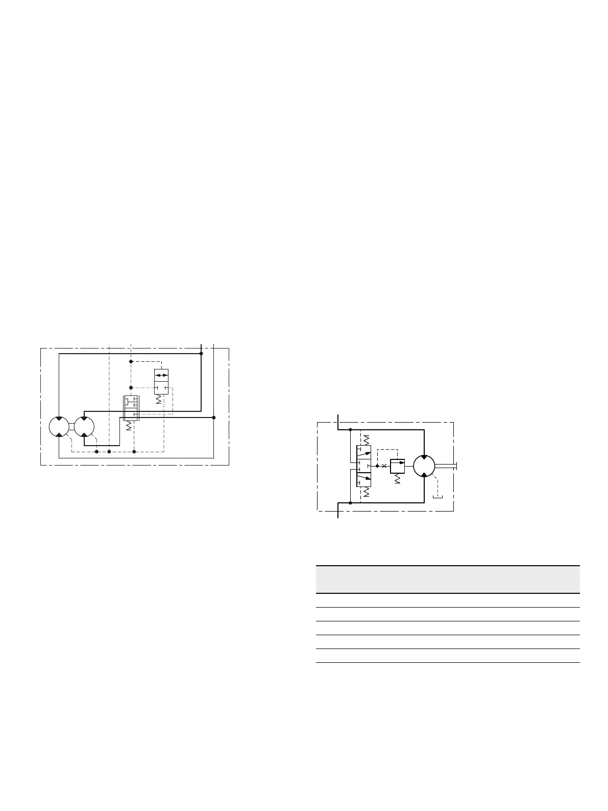
Two speed operation (2W)
In mobile applications where vehicles are required to oper-
ate at high speed with low motor loads, the motor can be
switched to a low-torque and high-speed mode. This is
achieved by operating an integrated valve which directs
hydraulic fl uid to only one half of the motor while continu-
ously re-circulating the fl uid in the other half. This “reduced
displacement” mode reduces the fl ow required for a given
speed and gives the potential for cost and effi ciency
improvements. The motor maximum speed remains
unchanged.
Bosch Rexroth has developed a special spool valve to allow
smooth switching to reduced displacement whilst on the
move. This is known as “soft-shift” and is a standard fea-
ture of 2W motors. The spool valve requires either an addi-
tional sequence valve or electro-proportional control to
operate in “soft-shift” mode.
▼ Schematic
AB
X
L
15 bar
12 bar
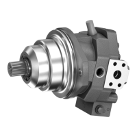
Flushing valve
In a closed circuit, the same hydraulic fl uid continuously
fl ows between the pump and the motor. This could there-
fore lead to overheating of the hydraulic fl uid.
The function of the fl ushing valve option is to replace
hydraulic fl uid in the closed circuit with that from the reser-
voir. When the hydraulic motor is operated under load,
either in the clockwise or counter-clockwise direction, the
fl ushing valve opens and takes a fi xed fl ow of fl uid through
an orifi ce from the low pressure side of the circuit. This
fl ow is then fed to the motor housing and back to the reser-
voir normally via a cooler. In order to charge the low pres-
sure side of the circuit, cool fl uid is drawn from the reser-
voir by the boost pump and is fed to the pump inlet through
the check valve. Thus the fl ushing valve ensures a continu-
ous renewal and cooling of the hydraulic fl uid. The fl ushing
feature incorporates a relief valve which is used to maintain
a minimum boost pressure and operates at a standard
setting of 14bar (other options available on request).
Diff erent orifi ce sizes may be used to select varying fl ows of
fl ushing fl uid. The following table gives fl ushing rate values
based on a boost / charge pressure of 25 bar.
▼ Schematic
A (B)
B (A)
Flushing fl ow rates
Flushing code Orifi ce size Flow [l/min] at 25 bar
1)
[mm] min max
F1 Ø1 2.2 2.7
F2 Ø1.5 5.0 6.1
F7 Ø1.7 6.4 7.8
F4 Ø2 8.2 10.7
F6 Ø2.3 8.8 11.4
1) 0.6 mm Shim (Standard), Cracking pressure = 11±3 bar