4/8 Bosch Rexroth AG Hydraulics
VT 3006 RE 29926/10.06
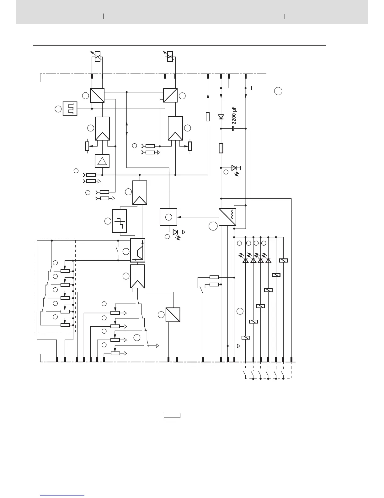
Block circuit / pin allocation
Positive comm. value
controls solenoid „B“
Negative comm. value
controls solenoid „A“
External ramp
Command value 5 ±6 V
Command value 4 ±9 V
Command value 3 ±9 V
Command value 2 ±9 V
Command value 1 ±9 V
Command value 6 ±10 V
Refer. potential
Differential
input
Aux. voltage ±9 V
Measuring zero (M0) is
raised by 9 V compared to
0 V operating voltage!
Call-up command value 1
Call-up command value 2
Call-up command value 3
Call-up command value 4
Call-up „Ramp Off“
Call-up „Switch-over aux. voltage“
Relay call-up voltage (+24 V)
Current command value at „w“
0 to +6 V for solenoid „A“
0 to –6 V for solenoid „B“
Current actual value I
A
at „I
A
“
Current actual value I
B
at „I
B
“
Biasing current
solenoid „A“
Biasing current
Solenoid „B“
Solenoid „A“
Solenoid „B“
Comm. value
after ramp
Operating
voltage
H1 to H4
=
LED-display for comm. value call-ups
H11
= „Power on“
H12
= „Ready for operation“
K1 to K6
= Call-up relais
R1 to R4
=
Command values
t1 to t5
= Ramp times
1
Command values
2
Differential input
3; 6
Summator
4
Ramp generator
5
Step function generator
7
Current output stage
8
Pulse generator
9
Monitorings
10
Power supply
F = on front plate
For explanation of
jumpers (J5, J6) and
arrangement of indi-
cator and adjustment
elements, see page 6