Hydraulics Bosch Rexroth AG
RE 29926/10.06 VT 3006
7/8
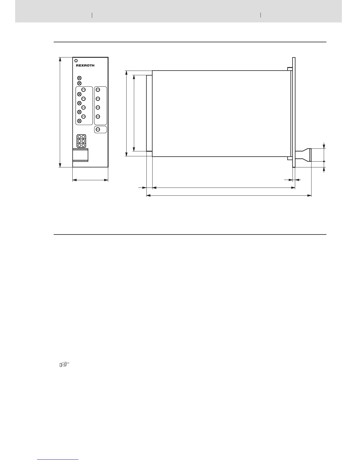
Unit dimension (Dimensions in mm)
Engineering notes / maintenance instructions / supplementary information
– The amplifier card may only be plugged in or unpluged when switched off!
– Do not use plugs with free wheel diodes or LED displays when connecting the solenoids!
– Only carry out measurements on the cards with instruments R
i
> 100 kΩ!
– Measuring zero (M0) is raised by +9 V compared to 0 V operating voltage and is not potentially separated , i.e. –9 V
controlled voltage is equivalent to 0 V operating voltage. Therefore do not connect measuring zero (M0) to 0 V operating
voltage!
– When switching command values use relays with gold contacts (small voltages , small currents)!
– When switching card relays only use contacts with a loadability of approx. 40 V, 50 mA!
When controlling externally the control voltage may have a maximum residual ripple of 10 %!
– Always screen command value lines; connect screen to 0 V operating voltage on the card side, other side remains open
(danger of earth loops)!
Recommendation: Also screen solenoid lines!
Use cable type LiYCY 1,5 mm
2
for solenoid lines of up to 50 m in length.
For longer lengths please consult us!
– Minimum distance to arial lines, radio sources and radar equipment must be at least 1m!
– Do not lay solenoid and signal lines near power lines!
– Because of the loading current of the smoothing capacitor on the card pilot fuses must be slow!
– Note! When using the differential input both inputs must always be switched on or off simultaneously!
 Loading...