1307SDH_RDH--EN,page 8/32
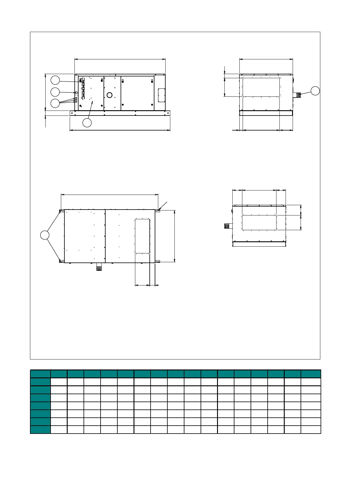
Figure 2.4 : RDH model-with integrated filter cabinet
OM
P
O
L
C1
100 N
E1
K
TS
UQR
A1
Suspension Points
B
Suspension Points
dia 11
VP
1. Combustion Inlet Air.
2. Combustion Outlet Air.
3. Electrical Connections.
4. Gas Connections.
5. Service Panel.
6. Suspension Points.
All Dimensions are in mm.
Tolerance All Dimensions `3 mm.
5
3
4
2
6
SIDE VIEW
FRONT VIEW
TOP VIEW
REAR VIEW
1
RDH A1 B C1 E1 K L M N O P Q R S T U V
025
1990 806 1860 2060 840 212 600 753 120 300 502 270 380 81 68 121
030 1990 1060 1860 2060 1094 212 700 753 197 300 756 270 380 81 68 121
035 1990 1060 1860 2060 1094 212 700 753 197 300 756 270 380 81 68 121
043
2430 806 2300 2500 840 229 600 988 120 500 502 270 615 81 68 121
055 2430 806 2300 2500 840 229 600 988 120 500 502 270 615 81 68 121
073 2430 1234 2300 2500 1268 229 1000 988 134 500 629 365 615 81 274 121
100 2430 1434 2300 2500 1468 229 1200 988 134 500 820 373 615 81 275 121
1. Combustion inlet air
2. Combustion outlet air
3 Electrical connections
4 Gas connection
5. Service panel
6. Suspension points
All dimensions are in mm.
Tolerance all dimensions 3mm
 Loading...
