1103UDSA-2--EN, Pag. 7/36
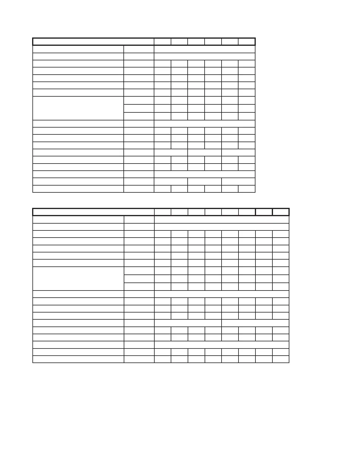
Table 4b : Technical data
1)
Gas Appliance Classifi cations for Approved Venting Methods based on CEN-report CR1749:2001.
2)
There is a difference between the gas connection diameter and the diameter of the supply line.
Always use the most adequate dia of the supply line to
minimize the pressure drop through the gas pipes - if necessary, reduce the diameter of the supply line at the inlet of the unit.
3)
Height from fl oor to bottom surface of heater.
These are recommendations only. Positioning of unit heaters for proper performance is application
dependent. Operation is affected by other air moving equipment in the space, obstructions to the airfl ow, draughts and/or close proximity to doors or
windows, etc ... Care should be taken to avoid mounting the heaters above these recommendations, unless downturn nozzle options are used, as
signifi cant stratifi cation may occur resulting in poor fl oor coverage and higher energy losses through the roof structure.
4)
Isothermal conditions +/-20°C ambient air temperature, discharge louvres zero defl ection, v = 0,5m/s.
The air throw will be infl uenced by the height
of the building, mounting height of the unit, ambient temperature & adjustment of the louvres.
5)
Sound pressure measured in
dB(A) : at 5m distance of the heater with
A=160m² & Q=2
TYPES 008-2 → 030-2
Type 008-2 011-2 015-2 020-2 025-2 030-2
Comb. Air & Flue, type B instal.
1
B22
Comb. Air & Flue, type C instal.
1
C12, C32, C42, C52, C62, C82
Flue & combustion air connection collars mm 80 80 80 80 100 100
Heat input (Hs) kW 8,8 13,2 17,6 22,0 30,8 35,2
Heat input (Hi) kW 7,9 11,9 15,9 19,8 27,8 31,7
Heat output kW 7,3 11,0 14,6 18,2 25,5 29,2
Thermal effi ciency % 92 92 92 92 92 92
Gas consumption rate
nat. gas G20
prop. G31
m
3
/h 0,84 1,26 1,68 2,10 2,94 3,36
kg/h 0,62 0,93 1,24 1,55 2,16 2,47
Gas connection size (not supply line size)
2
1/2”
Temperature rise K 32 32 32 32 32 32
Airfl ow m
3
/h 680 1020 1360 1700 2385 2725
Motor speed rpm 1390 1390 1450 1450 930 930
Recommanded mounting height
3
m 2,5 3,0 3,5
Horizontal air throw
4
m 8 10 13 16 20 22
Sound pressure
5
dB(A) 47 46 47 48 50 51
Electrical service (protection class IP20)
230/240V 1N 50 Hz
Total electrical rating W 121 126 273
Weight (net) kg 30 33 38 40 56 60
TYPES 035-2 → 100-2
Type 035-2 043-2 050-2 055-2 064-2 073-2 085-2 100-2
Comb. Air & Flue, type B instal.
1
B22
Comb. Air & Flue, type C instal.
1
C12, C32, C42, C52, C62, C82
Flue & combustion air connection collars mm 100 100 100 130 130 130 130 130
Heat input (Hs) kW 42,2 50,8 58,6 66,0 77,7 88,0 102,7 117,3
Heat input (Hi) kW 38,0 45,8 52,8 59,5 70,0 79,3 92,5 105,7
Heat output kW 34,9 42,1 48,6 54,7 64,4 73,0 85,1 97,0
Thermal effi ciency % 92 92 92 92 92 92 92 92
Gas consumption rate
nat. gas G20
prop. G31
m
3
/h 4,02 4,85 5,59 6,30 7,41 8,39 9,79 11,18
kg/h 2,97 3,57 4,12 4,64 5,46 6,18 7,21 8,24
Gas connection size (not supply line size)
2
3/4”
Temperature rise K 29 28 28 28 28 28 28 28
Airfl ow m
3
/h 3510 4535 5180 5830 6810 7770 9065 10360
Motor speed rpm 950 950 950 950 900 900 900 900
Recommanded mounting height
3
m 3,5 4,0
Horizontal air throw
4
m 2528303033353639
Sound pressure
5
dB(A) 55 54 55 56 56 58 59 59
Electrical service (protection class IP20)
230/240V 1N 50 Hz
Total electrical rating W 333 490 490 490 678 848 848 848
Weight (net) kg 88 99 99 112 118 143 158 168