1103UDSA-2--EN, Pag. 28/36
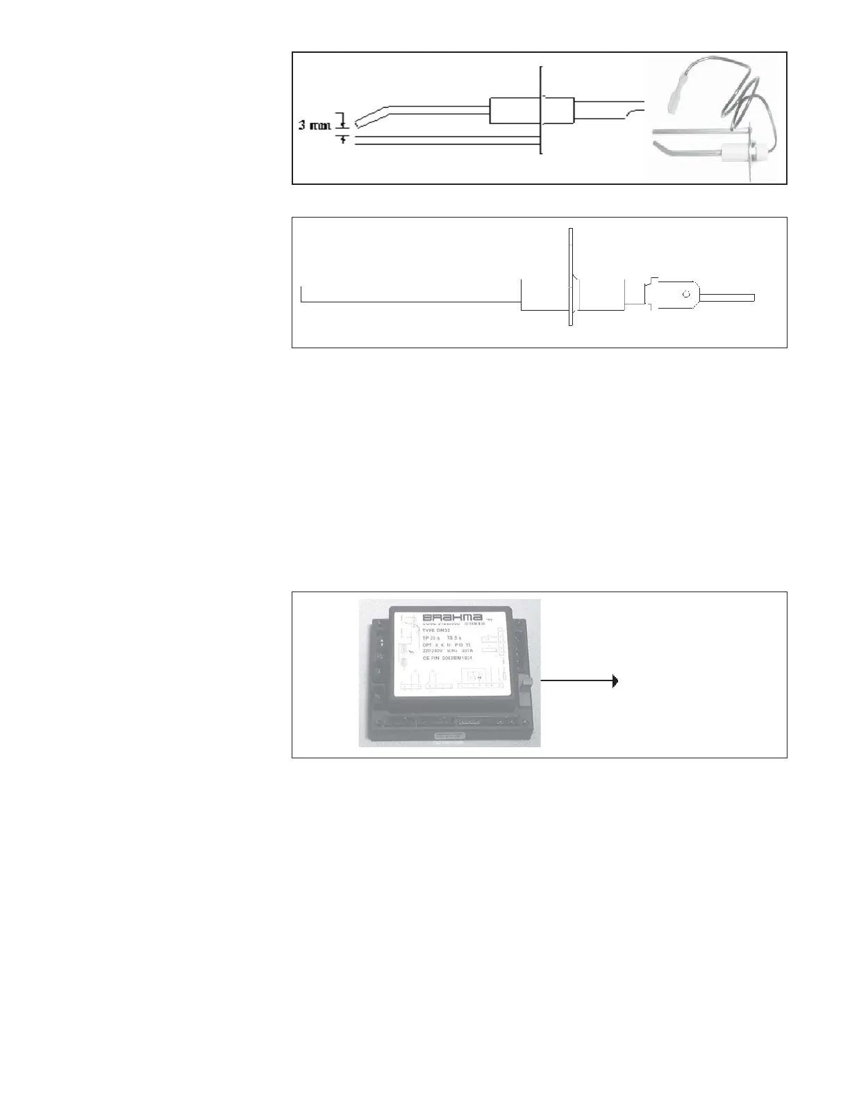
Figure 17 - Control relay
Fuse
Flame sensor - Refer to fi gure 11a and locate the fl ame sensor. Disconnect the
wire, remove the screw and the fl ame sensor. Clean with an emery cloth..
Control relay - See fi gure 17. The electronic burner relay monitors the operation
of the heater including ignition. Do not open the control relay. Each heating season
check the lead wires for insulation deterioration and good connections.
Proper operation of the direct spark ignition system requires a minimum fl ame
signal of 1.0 microamps (DC) as measured by a microammeter.
For further information and check out procedure on the direct spark ignition system,
refer to section 12 and the Troubleshooting Flow Chart in section 25.
Figure 16a
Ignitor showing required
spark gap measurement
Remove dirt and grease from the motor, the fan guard, and blades. Use care when
cleaning the fan blades to prevent causing misalignment or imbalance. Check that
the hub of the fan blades is secure to the shaft.
Follow these instructions for replacement of the fan guard, fan motor and/or fan
blades.
1. If the heater is installed, turn off the gas and disconnect the electric power.
2. Open the access door and disconnect the fan motor wires.
Flame sensor
Caution : Due to high
voltage on the spark wire
and electrode, do not touch
when energized.
18. Fan motors
The fan motor is equipped with thermal overload protection of the automatic
reset type. Should the motor fail to run, it may be because of improper voltage
characteristics. Make certain that the correct voltage is available at the motor.
Figure 16b
19. Fan motor,
Fan blades
&
Guard